Building a bandsaw on the cheap from mostly scrap wood
This is a placeholder.
I plan to come back and update this thread from the start to show the process of me building a band saw.
But for now, here's a picture of bearings being glued to the unfinished wheels.
[ATTACH]55778[/ATTACH]
Popdigr just bought a pawn shop table-top bandsaw for $30.
That man can find some deals, he can...
The #1 secret of getting deals is having cash, with you, right there in your pocket. Driving a vehicle you can take it home on the spot is #2.
I've had too many people back out given time to think about it, or a buddy tell them they could have gotten more, while I went to the bank or borrow a truck.
Damn, I just took a peek at Craigslist. $125 for a beautiful old Craftsman.
I had been looking at craigslist around here for a while and there are no tool deals at all. Tools can be found, but good ones are rare, and they are overpriced. I think it's because there is almost no industry in this town, so you don't get that critical mass you need to support that market. Plus I don't have a truck to run out and pick up a tool within hours of seeing it posted online.
This band saw will hopefully wind up costing about $200, including the brand new motor, bearings, and steel shaft from Ebay. The wood is mostly scrounged scrap wood, but I did need to buy about $50 of new pine boards for the frame. I'm at about $200 right now and I still need to buy some bolts and knobs and stuff, so tt might be $20-$50 more. I've gone through most of a gallon jug of glue already.
What I'll end up with is a 16" bandsaw, which would cost at least three times what I will spend. But this isn't about saving money. If I add the value of my time into the equation, I come out way behind. This is about having fun making something that should hopefully be pretty good when I'm done. In theory, I can make this tool be better than one I could buy. I won't know until I'm done, how good it is, but I'm hopeful.
And it's a big project. My goal is to finish in 2016. If I can keep up my current pace, I should be done by summer.
Shit, the braggin' rights alone is worth at least grand. :thumb:
This will allow you to level up significantly on the DIYS cred. I love that you're giving your kid this experience.
What's your game plan for balancing the wheels?
I'm going to spin them on their shafts and turn them down to size with a chisel, just like on a lathe, and then balance them by putting them on little roller blade ball bearings on a screwdriver, and just remove wood as needed with a forstner bit until they are balanced. They will look a little ugly with holes drilled in them, but they will work well.
This project is building a band saw based on plans by Matthias Wandel. I wish I could take credit for designing this band saw, but that would be a considerably more time consuming undertaking. I paid $21 to Matthias for the plans, and despite numerous spelling errors throughout, the plans are very detailed and helpful. I’ve deviated from the plans in a few places, but only in the techniques I use to do the same thing.
I share some of the same concerns as UT in wondering if it’s a bit self-centered of me to post a diary style thread, but I figure people can skip it if it bores them. This is a big part of my life now, and it’s important to me now, so I’m sharing it.
OK. Let’s get this thread started for real.
Sunday, 2/14/16
I come back from Home Depot with a gallon jug of glue and a bunch of boards. I spent a lot of time scratching my head in HD trying to figure out what boards to buy. They didn’t have the sizes I expected, so I did a lot of rough calculations standing in the aisle. Turns out I bought too much.
[ATTACH]55802[/ATTACH]
Monday, 2/15/16 Presidents Day!
I spent all day cutting everything for the frame to the correct size and width. I made a lot of sawdust. The frame is sandwiched lumber of varying sizes so that the joints overlap as you build up the frame. Great idea, but it means every piece is pretty much a custom piece. It’s getting complicated, so I label every part.
[ATTACH]55803[/ATTACH]
This is the plan on top of some of the boards I haven’t cut up yet. The plan prints out over multiple pages and my son and I used a glue stick to glue this together at the dining room table.
[ATTACH]55804[/ATTACH]
Sunday, 2/21/16
You can see that I’ve taken a few of the pieces and cut them into triangles. Seems simple, but I have to pay attention to make the grain go the same direction as the hypotenuse in the triangle. This makes the frame stronger and requires that I cut the other two legs. I want a frame with tight fitting joints, so I take my time and try to cut the triangles as accurately as possible.
[ATTACH]55805[/ATTACH]
Saturday 2/27/16
It’s the next weekend and time to start gluing these pieces together into a frame. I decide that instead of clamping all these layers together, I’m going to screw them together as the glue dries. This is a utilitarian machine and I don’t need a furniture quality finish to the thing. It’s much more important that this frame is nice and flat and square, and by using screws, I can just build the frame up from a flat bottom layer. To ensure it’s pretty flat I use the cast iron table saw top as the glue up table. I lay everything down on the full sized frame plan to make sure everything lines up correctly. Here you can see the table saw in the background with the frame starting to be laid out, and all the pieces lying on my workbench waiting for their turn. Some in the middle have slightly complicated notches cut in to them
[ATTACH]55807[/ATTACH]
Laying the first layer out on the table saw. Making sure it’s lined up just right. You can see the light colored board is just slightly thinner than the darker boards. I hadn’t really noticed this yet, and it’s going to be a pain later.
[ATTACH]55806[/ATTACH]
Sunday 2/28/16
The gluing is really going forward this next day. I used screws that are designed for pocket holes. They have almost ¾ of an inch of unthreaded shank and then about ¾ of an inch of thread. And they are flat headed with a sort of built in washer. Perfect for pulling the top layer down onto the lower layer. These screws are self tapping, but I drilled pilot holes because I was shifting the boards around when I tried to just use the self tapping feature. It required too much force.
[ATTACH]55808[/ATTACH]
This is when I added the third layer later in the day. It took a couple hours for the first layer of glue to dry enough to take all those screws out and reuse them to glue down that third layer with a second glue joint.
[ATTACH]55809[/ATTACH]
I used a lot of glue because I was noticing little gaps here and there between layers and I wanted the joints to be strong. So there was a lot of squeeze out of glue. This is why I put plastic down onto the tablesaw surface first.
[ATTACH]55810[/ATTACH]
Saturday 3/5/16
I got a straight edge out to see what was happening and realized that I’d have even stronger joints if I planed down the high spots after each layer had been glued on. So I started planning down high spots and testing the fit on the next layer. After this, the layers fit each other much better.
[ATTACH]55811[/ATTACH]
I glued down a fourth layer.
[ATTACH]55813[/ATTACH]
And after it dried and I took out the screws, I planed that surface down to prepare for a fifth layer.
[ATTACH]55812[/ATTACH]
I glued down another layer or two, but didn’t take pictures of those.
Sunday, 3/13/16
I was basically done with the frame and used scrapers and planes to clean up glue squeeze out and make sure the frame surfaces were level, plumb, and/or square as needed.
Then it was time to make the wheels. I had tons of scrap quarter inch luan plywood that was 25 years old or more. I had pulled it off the poorly finished basement ceiling when we bought the house and just stacked it in the corner. I used several sheets to build a kayak 15 years ago, and now I’m making a band saw with some more of it.
I took a pair of dividers and taped a pencil to one leg to make a large compass. I drew a bunch of slightly large circles on a scrap of plywood.
[ATTACH]55814[/ATTACH]
Then I used a nice compass to draw a smaller circle that will be the same diameter as a flange for lining stuff up later. And I drew a medium sized circle to locate the 4 clamp holes later.
[ATTACH]55815[/ATTACH]
I cut these circles out square and glued them up, alternating the grain direction of the outside surface of plywood. I used lots of glue again. I want these to be glued well, and I’ve got a gallon of glue.
[ATTACH]55816[/ATTACH]
Maybe I used too much glue. :) Better too much than too little here. What a mess!
[ATTACH]55817[/ATTACH]
Wednesday 3/16/16
It’s a Wednesday, but in an unprecedented move, the DC Metro system decided to give me a day off. Thanks, guys!
I’m getting better at the amount of glue I use. I’m still deliberately using too much, but at least it’s not ridiculous any more. Here, I’m working on what will be the other wheel. I used layers of quarter inch birch plywood for this one. I don’t remember where this plywood came from, but it’s cleaner looking. I think I was more careful with the glue this time so I could keep the pretty wood pretty.
[ATTACH]55818[/ATTACH]
Saturday 3/19/16
I double checked the plans, and my wheel blanks aren’t thick enough. So I glue another quarter inch of plywood to each one.
[ATTACH]55819[/ATTACH]
Thursday 3/24/16
It’s spring break, and I’m back from college tours with the family.
I use a handheld saber saw to cut a rough wheel for the bandsaw. I cut it slightly oversized so I can fine tune it later on its axis.
[ATTACH]55820[/ATTACH]
There’s sawdust blocking the view, but check out that edge. Gluing these thin sheets of plywood really resulted in a nice end product. These wheels will be nice.
[ATTACH]55821[/ATTACH]
Thursday 3/24/16 continued
I drilled a hole in the center, ¼ inch wider than the shaft is. There will be an eighth of an inch between the shaft and the wheel on each side.
[ATTACH]55822[/ATTACH]
Each wheel has flanges that are glued to it, and there are spacers to push the flanges out to the sides a little and make the wheels really steady. I cut the flanges to size and drilled holes in them to accept the shaft and bearings.
[ATTACH]55823[/ATTACH]
The bearings are pressed in to the wooden flanges and just held there by friction. I used a 2 inch forstner bit to cut the hole for the 2 inch outer diameter bearing. The bearing can be easily pushed through the hole with my fingers. It’s a nice fit once you line it up, but it just slides right through the hole.
[ATTACH]55824[/ATTACH]
Thursday 3/24/16 continued
The bearing is supposed to be really tight. Like, you have to press or hammer it in to place. You don’t want it coming out easily or the wheel might fall off. I get the idea to use a paper shim. It’s just the right size. With a paper shim wrapped around it in a single layer, the bearing needs to be hammered into place.
[ATTACH]55825[/ATTACH]
Hammering in
[ATTACH]55826[/ATTACH]
In place snugly
[ATTACH]55827[/ATTACH]
Before cleaning up the extra paper with a razor.
[ATTACH]55828[/ATTACH]
Thursday 3/24/16 continued
I carefully put glue on the flange, keeping the glue to a minimum and keeping the glue away from the bearing. The last thing you want to do to a beautiful brand new bearing is get glue in it. So I do the best I can centering the flange on the hole in the wheel and I clamp it down to dry. It won’t be perfect. It will be slightly off center, but that’s OK. We will fix that later.
[ATTACH]55829[/ATTACH]
And here is the other flange getting glued to the spacer so it will be ready for the other side of the wheel when we get to that point.
[ATTACH]55830[/ATTACH]
And here we see that no glue got in the bearing. Good. Also, these are some clamps I made to use when building my kayak. You take a PVC pipe, and cut one inch segments off of it. Then you cut a kerf into the offcut. You can pull it open, and it wants to spring closed. It has about as much force as a spring clamp, and when you need 30 spring clamps, it’s a lot cheaper to buy a pipe and make them than to go out and buy that many clamps. They are very handy.
[ATTACH]55831[/ATTACH]
Friday 3/25/16
This happens to be the 25th anniversary working at my firm, and I celebrate by continuing my spring break vacation.
Glue is dry on the first flange on each wheel, and now I’m about to put the second flange on. This second flange will determine how much the wheel wobbles, so I wait to glue it on until the first flange is dry. I carefully apply the glue, away from the bearing.
[ATTACH]55832[/ATTACH]
Then I mount the wheel with the second flange and I clamp it with 2 clamps. Moderate tightness.
[ATTACH]55834[/ATTACH]
Then I spin the wheel and check to see how much it wobbles from side to side. If it is crooked, I give it a whack with my mallet until it is straight. Then, I tighten those two clamps down, and add two more.
Here I am checking the wobble by seeing if this gap gets bigger and smaller. The wheel edge looks cool.
[ATTACH]55833[/ATTACH]
Friday 3/25/16 continued
With the wheels drying, I turn my attention to the big lower bearing block that holds the shaft to the frame. This is a big hunk of wood, and to cut it, I need my 10 inch saw blade. That blade is filthy with sap encrusted wood stuck in all the teeth, so I clean it in the utility sink. It will do a much better job of cutting if the teeth are clean. Not an interesting picture but important. I use oven cleaner.
[ATTACH]55836[/ATTACH]
And this is the block of wood I wanted to cut up so I could glue it to itself. This was an offcut from a Klondike derby sled axle I made for Scouts, and before that, it was a pole for teaching lashing. It’s been around and has some grass stains on it. Now it will be a band saw.
[ATTACH]55835[/ATTACH]
I turn my attention to the big drive pully that will be attached to the lower wheel. It’s basically yet another wheel to make, so I cut up some more scrap luan.
[ATTACH]55837[/ATTACH]
And I glue it up, alternating the grain pattern.
[ATTACH]55838[/ATTACH]
Sunday 3/27/16 Happy Easter!
The block is finished. It has a one inch diameter hole, the same size as the shaft diameter. This one is a tight fit, but I’ll add a clamp later for good measure. This has four bolt holes to bolt it to the underside of the frame’s lower cross member. If it’s out of alignment, I can loosen it and shim it, so it should be a good system.
[ATTACH]55839[/ATTACH]
I take the clamps off the pulley blank and cut it out.
[ATTACH]55840[/ATTACH]
Cut out pulley.
[ATTACH]55841[/ATTACH]
Sunday 3/27/16 continued
The pulley doesn’t fit over the flanges on the wheel. I hadn’t eased the corners on my flanges enough! So I trace the inside of my pulley and cut off the glued down flange corners. I need to use a chisel to clean up the glue and pry up those cut off corners.
[ATTACH]55842[/ATTACH]
All the corners trimmed
[ATTACH]55843[/ATTACH]
And the pulley fits now! I still need to trim down the outer diameter of the pulley and carve a notch in it for the v-belt.
[ATTACH]55844[/ATTACH]
Sunday 3/27/16 continued
I glued up a few maple boards to make blanks for some other pieces: The guide bar and the guide bar clamping block. Now they just look like wood scraps glued together.
[ATTACH]55845[/ATTACH]
This are the plans I’m following to make these two pieces
[ATTACH]55846[/ATTACH]
Wednesday evening 3/30/16
I need to make another wheel shaped object! This time it’s a temporary drive pulley to drive the wheels and other pulley to make those guys round and nice. This temporary one is fairly crappy, but that’s OK. I cut it out on the jigsaw. This piece started life as a particle board piece of disposable furniture.
[ATTACH]55847[/ATTACH]
And I cut this v-belt groove with a stacked dado head cutter in the table saw. I clamped the fence down the proper distance from the blade, and then clamped a wooded board to the table saw surface to act as a fence on the other side of the pulley. I rotated the pulley on the raise dado cutter. Kind of worrisome because I had never done that on a table saw before, but I kept my hands clear and I don’t think there was much chance of kickback.
[ATTACH]55848[/ATTACH]
Wow. What an excellent job and creative approaches to clamping and machining.
One thought about balancing the wheels, drilling is how it is done with steel and aluminum wheels but since you are using wood you could tack bits of lead or steel washers to the wheel, this would allow you to avoid possibly removing too much material and would make an iterative and tedious process a lot quicker.
This is going to be great.
In that last picture, I was a little annoyed to see there was a hidden metal staple or something in that particle board. The edge of the particle board had solid wood banding, and that was some sort of hardware to help connect the two. I didn't closely examine the carbide tipped stacked dado cutter as I removed it, but cutting through staples can't be good for it.
Or drill a small hole at the light spot, fill it with lead, then drill the lead until it's just right. Maybe the tire store will spin it on the balance machine.
Or drill a small hole at the light spot, fill it with lead, then drill the lead until it's just right. Maybe the tire store will spin it on the balance machine.
That thought crossed my mind too.
In that last picture, I was a little annoyed to see there was a hidden metal staple or something in that particle board. The edge of the particle board had solid wood banding, and that was some sort of hardware to help connect the two. I didn't closely examine the carbide tipped stacked dado cutter as I removed it, but cutting through staples can't be good for it.
Lo siendo! Staple no es mas macho que carbide.
Cement, on the other hand...
Monday night 4/4/16
The plans call for a 47 inch long v-belt to drive this thing. After a scout meeting last night, I swung by Advanced Auto to buy a belt. They don't keep the belts out front, and they don't organize the belts by size. You have to know you car model and what kind of belt you need for your car. They look it up in their system to get the part number, and they go back and get the belt.
The guy at Advance Auto was nice, he told me to just go in back and get what I needed, and pointed out where the ladder was if I couldn't reach. The belts didn't have consistent labeling. Some had dimensions, and some didn't. So I looked at all the belts and wound up just buying one that looked about the right size. I didn't have a tape measure, but the floor tiles I was standing on looked like they were a foot. So I bought a belt that almost reached across two tiles. Took it home and noticed tiny printing on the side of the belt. 48 inches. I expect it will be close enough. I really only needed it right now to spin the wheels, and that is totally adjustable, so it would work for that.
I took a wheel. I screwed the temporary crappy finished particleboard pulley to one face, centering it as best I could. I screwed the permanent nicer unfinished plywood pulley to the other face, centering it as best I could, using calipers to measure from the bearing edge at the center of the wheel. I mounted this wheel on my ƒucking METAL BAR, clamped everything down. Clamped a motor down. (I bought this 1/4 hp motor at a flea market years ago for $2. Using it now for the first time.) Put the belt on, and fired the sucker up. It spins nice and quiet. It's nice. I clamped down a tool rest and tried cutting a little bit.
[ATTACH]55901[/ATTACH]
It was too late at night to really give this the attention it deserved, but I played with it for about a minute.
[ATTACH]55899[/ATTACH]
[ATTACH]55900[/ATTACH]
This is gonna work! The bar is clamped a little loosely and sways a little bit back and forth. I'll fix that before I begin seriously shaping the edges of the wheels and drive pulley.
Very good. The auto parts stores drive me crazy with that shit, but I guess they've adjusted their business model to their customer base's knowledge... clerks too. But when the data entry into their system is wrong it's a pain in the ass.
I stopped to pick up something at pep boys one time, and coming out of the store noticed something hanging down under the car. It was a belt that had split with the inside half in place but the outside half had come off. Strange failure. Well the outside half had the size printed on it so I took that back in and told the guy what size I needed. He starts the make, model, year thing, telling me it's the only way he can find it. Then he brings out a belt 6 or 8 inches too long, and argues with me when I've got the right size in my hand. It was a Plymouth Horizon, but to get the right size he had to enter Dodge Omni, which was identical, but somebody had screwed the system.
My old hardware store had a belt measuring tool. You bring in the belt, they measure it and you get the size you need. I think it disappeared when computers made everything so much more better.
Yes, I've used one of those many times, some stores kept them long after the computers took over, but kept them hidden in the back not to anger the IT overlords. They're ok when the size has worn off, but a lot of people didn't have a belt to bring in, didn't know there was a problem until the belt was long gone. The manufacturers confused the issue when they started using belts of different widths, and in an effort to make the whole package more compact, designed in less than an inch of adjustability.
This thread are interesting.
4/7/16
Last night I reconfigured the way I had the steel shaft clamped down. I removed the sloppiness that was there before, so the bar isn't swaying 1/8th of an inch back and forth with each turn of the wheel. It's rock solid now. I turned the wheels a little bit more, but was very tentative because I didn't know how much material to take off. I knew the wheels were a little oversized, but during glue up, the plywood panels had shifted around slightly, and it was possible some spots on the edge didn't have much material left for me to remove.
So I looked up what the finished diameter was supposed to be, and I measured the circumference with my wife's cloth tape measure, and see I have about 2 inches of circumference or so to remove, and around a quarter inch of radius to remove. So I can be less tentative about this and really make some sawdust. The size of the wheel doesn't have to be exact, but the two wheels do need to match one another pretty much exactly or the band saw blade will not be plumb.
Working for 20 minutes or so during random evenings after work, you don't make much progress. Hopefully I'll get some real work done this weekend.
Nothing like the weekend for making a big mess to clean up. :haha:
The upside of the 20 minutes on random evenings is you get lots of time to think about it in between. Going over the things to do and the right order, you may spot a flaw in your plans, or think of a better way. Either way, you'll get it done and we'll be here to watch.
Working for 20 minutes or so during random evenings after work, you don't make much progress. Hopefully I'll get some real work done this weekend.
Slow and steady wins the race.
As long as there are no binder clips involved.:stickpoke
:p:
4/7/16
Last night I reconfigured the way I had the steel shaft clamped down. I removed the sloppiness that was there before, so the bar isn't swaying 1/8th of an inch back and forth with each turn of the wheel. It's rock solid now. I turned the wheels a little bit more, but was very tentative because I didn't know how much material to take off. I knew the wheels were a little oversized, but during glue up, the plywood panels had shifted around slightly, and it was possible some spots on the edge didn't have much material left for me to remove.
So I looked up what the finished diameter was supposed to be, and I measured the circumference with my wife's cloth tape measure, and see I have about 2 inches of circumference or so to remove, and around a quarter inch of radius to remove. So I can be less tentative about this and really make some sawdust. The size of the wheel doesn't have to be exact, but the two wheels do need to match one another pretty much exactly or the band saw blade will not be plumb.
Working for 20 minutes or so during random evenings after work, you don't make much progress. Hopefully I'll get some real work done this weekend.
You are adding rubber tires, yes? and crowning the wheel?
Yes and yes.
In fact, the beauty of this is that even if the wheel has a little wobble in it from warped plywood or whatever, when I crown the wheel, the crown will be centered so the wheel wobble doesn't matter. It may add a little vibration to the machine, but won't affect the blade tracking. The blade will ride the crown.
But you are getting ahead of yourself. I've barely begun to shape the wheel. Stop peeking into my brain!
I too am pleased with this thread. As you were.
But your brain is so mesmerizing!
4/9/16 Saturday (and my birthday)
Busy day today. Full of fun, and I even had about an hour to work on the band saw.
I started off by turning the wheel down a little bit more. I’d make what seemed like a lot of sawdust and flatten and square the edge, unplug the motor and then pull out my wife’s cloth tape measure and measure the circumference. Still a long way to go. It was taking a while, and I just wasn’t into it at the moment.
So I decided to shift my attention to something else. I was going to need to also turn down the pulley and make a groove in it for the v-belt, but the pulley was too far from the board I was using as a tool rest. No safe way to reach it with a chisel. I decided to make a tool rest extension. Pretty straightforward.
First I cut the vertical part. Then I drilled some holes in what would be the horizontal support.
[ATTACH]56095[/ATTACH]
Clamped the vertical tool rest part and used some of those pocket hole screws to screw it together.
[ATTACH]56096[/ATTACH]
Holding the tool rest in place to see how it will fit. It’s still not as close to the wheel as I would like, but it would be too much effort to set things up to get it closer.
[ATTACH]56097[/ATTACH]
4/10/16 Sunday
I had about half an hour after mowing the lawn, so I turned the wheel down some more. I’m pretty close now to the right size.
[ATTACH]56098[/ATTACH]
4/15/16 Friday afternoon
I had a solid hour after taking my elderly cousin to a doctor’s appointment and before dinner.
I started off by measuring. These plans are for a “16 inch band saw.” This size refers to the wheel diameter, but the plans are in metric because the guy lives in Canada and comes from Germany, so his plans actually call for wheels that are 40 cm in diameter. That works out to 15.75 inches. So they are a little smaller than a true 16 inch band saw. If you are measuring the circumference of a 40 cm wheel, after the metric to English conversion and doing the πr calculation to get the needed circumference, you find these plans call for a pair 49.478 inch circumference wheels. That was the number I was aiming for. The more I thought about it though, the more I realized the size just didn’t matter as long as it was close. The only thing that really mattered was that the wheels matched one another, otherwise the band saw blade would not be plumb and cuts would not be square. In fact, if I really wanted a true 16 in band saw, I should be shooting for a circumference of 50.265 inches. It was time to stop removing material.
[ATTACH]56100[/ATTACH]
Time to start shaping the pulley. The tool rest I made works pretty well. It’s not metal and the wood is denting a little as I rest the gouge against it, but I didn’t care. The tool rest only needed to last for a half hour or so. I smoothed the rough uneven surface of the pulley and made it round.
[ATTACH]56102[/ATTACH]
I got it nice and smooth. I didn’t worry about the diameter of the pulley. I could change the speed of the saw by adjusting the size of the pulley, but probably not by much, so I didn’t bother worrying about it. I didn’t even know what the speed should be and there were other variables that factored in to the speed that I could always change later.
[ATTACH]56099[/ATTACH]
And then I started cutting a notch for the v-belt. I just guessed at first but then compared it to the actual belt I had to fine tune it.
[ATTACH]56101[/ATTACH]
4/15/16 continued
The plywood wheel had a couple small voids in the core of one of the layers. Not a big deal.
[ATTACH]56103[/ATTACH]
I put some glue in the void.
[ATTACH]56104[/ATTACH]
I scooped up some sawdust from the turning, and dribbled some glue in it.
[ATTACH]56105[/ATTACH]
Mixed it together until I had a sticky blob.
[ATTACH]56106[/ATTACH]
4/15/16 continued
And I smeared the blob into the glue filled void. Pressing it in as deeply as I could with my thumb.
[ATTACH]56107[/ATTACH]
4/17/16 Sunday
After mowing the lawn, I had about an hour in the afternoon to play in the shop.
I cut the v-belt notch in the pulley a little deeper and wider.
[ATTACH]56108[/ATTACH]
I test the fit. It’s petty good.
[ATTACH]56109[/ATTACH]
I smoothed out my sawdust patches and got the wheel to its final outer diameter. Somewhere between 16 inches and 40 cm.
[ATTACH]56110[/ATTACH]
The plans called for a 5 degree bevel on each side, so I set the bevel gauge to 10 degrees total so I could eyeball things.
[ATTACH]56111[/ATTACH]
4/17/16 continued
I beveled each side a little and wound up with a slight crown. Pretty close to 10 degrees total, but I didn’t get a picture.
[4[ATTACH]56112[/ATTACH]
Then I grabbed some coarse sandpaper and a wooden block and sanded the edge of the wheel while it was spinning. This is my drive wheel basically finished. I need to varnish it and put a tire on.
[ATTACH]56113[/ATTACH]
Time to move on to the top wheel. I used a set of calipers to try to center the temporary pulley before I screwed it on.
[ATTACH]56114[/ATTACH]
Top wheel is almost done! This one went much faster. It’s birch plywood, I think, and cuts a lot easier than the luan plywood did. Remarkable the difference between the two.
[ATTACH]56115[/ATTACH]
4/9/16 Saturday (and my birthday)
I started off by turning the wheel down a little bit more. I’d make what seemed like a lot of sawdust and flatten and square the edge, unplug the motor and then pull out my wife’s cloth tape measure and measure the circumference. Still a long way to go. It was taking a while, and I just wasn’t into it at the moment.
Turning is messy, you could have roughed it in closer if you only had a bandsaw. :haha:
Seriously though, it's looking good, good work and good progress. :thumb:
You're knocking this off faster than expected.
This kind of project isn't my thing and I'm not following closely, but it's obvious you know what you're doing and are documenting it very nicely. And happy late birthday!
It's really wonderful to watch your progress and read your thoughts on this. Would having metric wheels cause a problem when buying blades or is there enough adjustment to the wheel to take up slack caused by a smaller wheel?
Could you mount one of the wheel axles on an adjustable base for fine tuning blade perpendicularity and as I am typing this I realized it is irrelevant because the table is adjustable. So even if your wheels are not perfectly sized and perpendicular that can be fixed. I guess the most important thing is that they lie on the same plane.
I can't wait to see it finished.
I vote that you take it to a body shop and have flames painted on it. And racing stripes. Candy apple red with metal flakes.
I want videos of you cutting up random shit with it when it's done. Like watermelons and old cell phones and James Bond action figures
Oh, and what's our total monetary investment at this point? I'm holding you to that On the Cheap part.
My recollection is that I'm at about $200 right now, but that may be a selective memory.
I paid for lumber when my original plan was to only use scrap wood. I have a lot of scrap wood, but using it for the frame would have been considerably more work because I would have to edge glue narrow pieces to get the wider pieces I needed, and then I'd want to thickness plane everything, but I don't have a thickness planer. Anyway, that was probably around $80 for the wood. I don't have the receipt anymore but I bet that's close. It was a medium grade pine that I used. Maybe cheaper. Maybe $50. Let's say $80 though. Look at that pile of wood at the beginning of the thread and you tell me what you think it cost.
The Everbilt 2-Speed 3/4 HP 115-Volt Evaporative Cooler Motor was $27.98 on ebay including shipping.
The 24" shaft and 4 bearings were from Amazon for $61.07.
The glue was about $20 from Home Depot.
Current total is about $190.
I forgot the belt, The belt was about $5.
$195.
I need to buy some hardware. Bolts, knobs, etc. And a blade.
Even if you end up spending as much as you could have bought a new one for, the fun of doing it and learning makes this a win.
True.
And the truth is also that I would never feel justified to buy one for several hundred dollars, but spending $50 here and there is totally justified.
Just spent $24 on hardware. These knobs are pricey.

Yes, that's why I tried to salvage bits and pieces like that whenever/wherever I could. I don't think you have many opportunities in a white collar office, but even heavy trash put out on the curb for collection have good shit like cords and hardware. having a stash provides a window of spontaneous solutions and creations, even after the stores are closed. The down side is the questions. What that for? Don't you have enough junk? What if someone sees you? :haha:
4/23/16 Saturday
Just spent an hour finishing the top wheel. Both wheels are the exact same size (49 and 13/16ths inches circumference, or 15.86 inch diameter wheels) and are crowned. Sanded them both and then put one coat of water based polyurethane one them. They are probably dry enough already for a second coat. I'll put a few coats on and then sand the finish smooth on the edge of the wheel. Tire will stick better to a smooth surface.
[ATTACH]56171[/ATTACH]
I also measured the frame and marked the exact center line that the axles need to line up on.
Do you have this book?
http://cllr.me/cn3I think you should pencil notes, dimensions, and an occasional appropriate curse on it, then clear coat. Give future generations a touchstone to their roots when you've become a shade tree. :thumb:
Do you have this book?
http://cllr.me/cn3
No. Do you recommend it? I should get a book. I have a fairly good understanding of them but there's definitely room for more knowledge.
I've only used a band saw once or twice and managed to break a blade in that time.
I like the clear coating over notes idea. I'll do that on the frame.
I've got two more coats down. It's finally starting to get a little smooth and the disposable sponge brush isn't snagging as much.
Do the plans give you a blade length?
Just wanna note the cool factor here. Well done!
Do the plans give you a blade length?
Yes. And there are a couple inches of adjustment when tensioning, so it doesn't have to be exact.
I had a bunch of blades I made at work. We bought the blade on a 50 or 100 ft roll, and there was a welder and grinding wheel built into each DoAll bandsaw, so we could make any length. When I added a 6" riser to my saw so they were a foot too short. I don't remember the length or even if I have any left, but if you give me a size I'll root around the cellar and see.
No. Do you recommend it? I should get a book. I have a fairly good understanding of them but there's definitely room for more knowledge.
I've only used a band saw once or twice and managed to break a blade in that time.
I like the clear coating over notes idea. I'll do that on the frame.
I've got two more coats down. It's finally starting to get a little smooth and the disposable sponge brush isn't snagging as much.
Absolutely. I think he may have an updated version of it, but this one is thorough and a must for troubleshooting. I re-read it the other night and discovered things I had missed the first seven times I read it. Also, new weird things are always cropping up of the "why is this happening all of a sudden?" variety and a passage that seemed irrelevant before suddenly becomes pertinent.
As Bruce mentioned welding blades, there is a whole section on welding blades, brazing, and silver soldering them.
I had a bunch of blades I made at work. We bought the blade on a 50 or 100 ft roll, and there was a welder and grinding wheel built into each DoAll bandsaw, so we could make any length. When I added a 6" riser to my saw so they were a foot too short. I don't remember the length or even if I have any left, but if you give me a size I'll root around the cellar and see.
Thanks Bruce! This saw takes a 105 - 106 inch blade, which is the size a 14inch saw with a 6 inch riser block would take, so it's a fairly common size. If you have any extra ones kicking around that you don't need, I'd be happy to take them off your hands. :biggrin:
I don't know if Franny really said this, but I like it.
4/24/16 Sunday afternoon I had an hour or two.
I mostly just straightened up the shop. The wheels are basically done. I'm going to put the tires on them before I balance them, and the tires (14 inch inner tubes) are coming this week some time. But I put away my wheel turning station and swept the floor, put tools away, etc. I was all out of empty horizontal surfaces and needed room to work.
But I did make some progress. I had an old bed frame I dug out of the neighbor's trash.
[ATTACH]56202[/ATTACH]
It's made of nice thick maple, used as a secondary wood, with some sort of tropical hardwood in the showy places. I tore off that tropical hardwood years ago, and it splintered badly so I threw it away. But I had these nice maple bed frames. I need a big hunk of wood to be the top bearing block, and it's a very intricate shape. So I cut up part of my bed frame and glued it up into a nice block. I wish I had a thickness planer. It would be easier to do this stuff.
[ATTACH]56203[/ATTACH]
[ATTACH]56204[/ATTACH]
It was getting to be dinner time so I stopped there. I'll make all the intricate cuts next time.
Yes. Yes it is. 11 clamps. Seems like a lot in hindsight, but at the time, it felt right.
Can't have too many clamps.
4/26/16 Tuesday evening. I got 1.5 hours in tonight because the kids were doing homework and my wife was at a meeting, so nobody would really notice if I scampered down to the workshop for a while.
I'm continuing to work on the top axle mount. I started off making cuts with the table saw, but the block was so big, I had to have the blade high, and I couldn't use a blade guard, and figuring out how to clamp the thing down was tricky. It just wasn't fun. And setting the angles and blade height was tricky, getting the calipers out.
So I switched to hand saws, and it was much more pleasant. Japanese pull saws are a joy to use.
So this is what I made tonight.
[ATTACH]56225[/ATTACH]
No problem, just throw that block in the CNC mill and watch it work, while shooting footage for utube. :lol:
But there ain't no bucket. ;)
5/14/16 Saturday - My wife and daughter drove down to Richmond to look at a college, and I stayed home to fix a leak I discovered when fixing the dishwasher last week, except the part hadn't arrived yet. So I had a whole day (five hours or so) to work on the band saw.
I found some more scraps of that maple bed frame I was using before. It's the PERFECT thickness for this next batch of parts. 3.2 cm thick.
First up is the frame that holds the shaft mount for the top wheel.
[ATTACH]56524[/ATTACH]
Each side of the frame is a different width and length, and the top and bottom need lips cut into them or holes drilled in them
[ATTACH]56525[/ATTACH]
My table saw's scale seems less exact at narrow widths, and it shifts slightly when I lock the fence down, so I use a caliper to measure things. Here, I'm setting up to cut notches in the ends of the side pieces. I think. Stop block on the miter gauge. One of these days I'll make a sled.
[ATTACH]56526[/ATTACH]
And this is the frame being glued up. After this dries, I'll cut 4 slots for splines in each corner. This needs to be a strong joint and it's way too weak glued up like this.
[ATTACH]56527[/ATTACH]
While that frame is drying, I turn back to the top shaft mounting block. It needs a 1 inch hole for the shaft.
[ATTACH]56528[/ATTACH]
And it needs a hole for the tracking adjustment bolt. A T-nut too.
[ATTACH]56529[/ATTACH]
This is with a sample bolt installed. Turning the bolt will tilt the mount and the shaft in the mount and will adjust the tracking of the blade on the wheels.
[ATTACH]56530[/ATTACH]
The mount goes in the frame I just glued up. And the frame is held to the big saw body frame with a couple of L brackets. So I made those L brackets.
[ATTACH]56531[/ATTACH]
And now I turn to balancing those wheels I made before. I decided that I didn't want to drill holes in the wheel. So instead of drilling holes in the heavy side, I added weight to the lighter side.
I drove screws into the pulley on the lower wheel. As I got closer to the balanced weight, I switched to smaller and lighter screws. Once when I put a screw in that was too heavy, I backed it out and put a smaller screw in. Not quite as ugly as a bunch of holes, and the pulley is held on better now.
[ATTACH]56532[/ATTACH]
And I forgot that I had picked up some inner tubes to use as tires. A 14 inch inner tube on a 16 inch wheel stays put pretty well. So I put these "tires" on the wheel, and checked the balance again.
The top wheel was in better shape. It only took a few screws to balance.
[ATTACH]56533[/ATTACH]
Thanks for documenting this project, Glatt.
Saturday 5/21/16 - 1 hour
I did some measuring of the frame and temporarily fit the lower shaft mounting block to the frame in its exact location.
[ATTACH]56649[/ATTACH]
I marked the location for drilling the holes for the lag bolts and then drilled them.
[ATTACH]56650[/ATTACH]
Sunday 5/22/16 – 5 hours. I got a big chunk of time this day to make some progress.
I had left the frame only partially constructed so a drill could fit into the space where the holes would be drilled for those lag bolts. Now it was time to finish gluing up the rest of the frame.
I had to trim some of the pieces I had pre cut because they were a millimeter or two too long for the frame as I had glued it up.
[ATTACH]56651[/ATTACH]
And this is the completed frame all glued up.
[ATTACH]56652[/ATTACH]
You are looking at the underside of the foot of the frame. That wide glued up slab is where the motor will be mounted. It looks a little uneven, and not exactly flat. In hindsight, I should have tried to glue it up on a solid surface. Oh well, if it is wobbly, I can shim it as needed to make it sturdy. I guess that’s the nice thing about making this myself out of wood. I can always add wood or take wood away as needed to make things flat and square.
Sunday 5/22 continued
I had made the frame for the top mounting block last time I was working on the band saw, and I need to reinforce the corners. It will be holding the tension of the blade, so the corner joints of this box need to hold a couple hundred pounds of force each. So I need to take those weak butt joints and reinforce them with splines. Kind of like making my own plywood.
I started by figuring out how to hold the frame at a 45 degree angle to the table top. I had picked up this knife storage block off the curb in front of my neighbors’ house on trash day years ago. They were moving out and put a ton of stuff on the curb. I never knew what I would use it for, but it seemed like it would come in handy some day. Today is that day. It’s my jig for holding the frame at 45 degrees. Here, I’m holding it next to the saw blade to set the blade height.
[ATTACH]56653[/ATTACH]
Next I put the fence in the right spot and visualized how the cut would go. I wasn’t happy with it. The fence was too short and the work piece wanted to rotate over the fence when I pressed it to the fence. It would ruin the cut and might cause a dangerous situation.
[ATTACH]56654[/ATTACH]
So I dug out an auxiliary tall fence I had made for a router table that I never use. This tall fence was made from a counter top I dug out of the trash at work. The counter was perfectly good, but they were redoing the space and tossed it. Nice melamine over very thick particleboard. I also put some blue tape on the knife block jig to tell me how high the blade was. This felt much more secure and sturdy. I’m happy with it.
[ATTACH]56655[/ATTACH]
So I made a bunch of cuts. 20 to be exact.
[ATTACH]56656[/ATTACH]
Sunday 5/22 continued again
With the slots cut, it’s time to make some splines. Through trial and error, I set the fence to the exact distance from the blade to get a good spline thickness. My zero clearance blade insert is critical here so the spline doesn’t fall down into the saw as it is cut. I used some of the last scraps of that maple bed frame to cut a few long skinny splines, and then cut them into triangles with the miter gauge.
[ATTACH]56657[/ATTACH]
And then I started gluing them into place. This was kind of messy. I got glue all over my fingers.
[ATTACH]56658[/ATTACH]
And while the glue on the frame splines dried, I turned my attention to the wheel shafts. I had bought a 2 foot fucking metal bar online, and needed to cut it to length. So I started with the lower shaft. It needed to be 20 centimeters. My son had been using the hacksaw a lot to make various zombie weapons and it had basically no teeth left anymore, so I put a nice new blade on. He saw me do this and was thrilled. The hacksaw will cut again!
[ATTACH]56659[/ATTACH]
I tried to rotate the cut of the hacksaw so it would be held by a thread of steel in the middle of the bar and wouldn’t have a nasty burr on the corner, but even so, the cut was a little rough and I had to file it smooth.
[ATTACH]56660[/ATTACH]
Sunday 5/22 continued yet again
I needed to keep the wheel from falling off the shaft when it was spinning on the saw, so I started by drilling a hole. (With my cordless, drill, incidentally.)
[ATTACH]56661[/ATTACH]
It was slow going, because I had to stop every 5 seconds or so to add more oil. The cuttings were flinging the oil off the end of the shaft. So I wiped off the shaft and made a duct tape dam to hold an oil reservoir.
[ATTACH]56662[/ATTACH]
Drilling was much faster now. And it was time to tap the hole with threads.
[ATTACH]56663[/ATTACH]
I’ve mentioned this before, but I always feel so badass when I’m cutting threads into something.
[ATTACH]56664[/ATTACH]
Sunday 5/22 the final chapter
And here I am screwing a big old washer to the end of the shaft.
[ATTACH]56665[/ATTACH]
It fits perfectly around the stationary center of the bearing but not the spinning outer ring of the bearing.
[ATTACH]56666[/ATTACH]
This is how the finished wheel will look mounted on the saw.
[ATTACH]56667[/ATTACH]
2 foot fucking metal bar
:lol:
Tapping threads is bad ass. It's like you're. ...well... I'll not go into that analogy. But I get you. This is coming along nicely. It must be difficult to constantly remember to stop and take pics along the way. It will be worth it though, in 20 years when your son wants to build one and you can just show him this thread.
I have one criticism, if you don't mind. Those screws you balanced it with need to be covered up. They're ugly and random looking. If you have to glue a veneer over them and counter balance that, I think you should. Hopefully you already planned to do that. I want this to be pretty too.
Sent from my SM-T530NU using Tapatalk
I have one criticism, if you don't mind. Those screws you balanced it with need to be covered up. They're ugly and random looking. If you have to glue a veneer over them and counter balance that, I think you should. Hopefully you already planned to do that. I want this to be pretty too.
I don't mind. I agree that the screws look like crap, but I'll be making a protective housing to cover the wheels, so these screws will only be visible when I am changing the blade. I can live with that. And this top wheel can be reversed so the screws for that one are on the back side and completely hidden.
This is great. You're kicking ass on this one ...
I'm still stuck on how much scrap wood you must have had
I don't mind. I agree that the screws look like crap, but I'll be making a protective housing to cover the wheels, so these screws will only be visible when I am changing the blade. I can live with that. And this top wheel can be reversed so the screws for that one are on the back side and completely hidden.
I figured you'd be on top of that.
This is great. You're kicking ass on this one ...
I'm still stuck on how much scrap wood you must have had
Heh. I still have a ton of scrap wood. I can't turn down halfway decent pieces of wood in the trash.
You went to town with those splines. Three per corner would have been overkill. Now you know where to go in case of an earthquake, under your bandsaw. hahaahhahahaha
Friday 5/27/16 - 45 minutes (after work, and before my wife and daughter get home from a college tour.)
Not pictured: Cutting the fucking metal bar to get a 17.5 cm top wheel shaft, drilling a hole in the end of it, and tapping threads into the hole. You can use your imagination, or look at the pictures of the same thing I did on the lower shaft last week.
Saturday 5/28/16 – 20 minutes in the afternoon. The glue had dried on the splines I put in the corners of the upper wheel mount frame, so I cut them off with a utility knife and used a scraper to scrape them flush with the surface of the frame. I will need nice flat surfaces to press against the fence later on the table saw. A belt sanding station would have been awesome, but I used a scraper because it’s what I have. Incidentally, I we just gave my son a bench top belt sanding station for his birthday today, so if I ever need to do this in the future, I can do it in a couple seconds on his belt sander.
[ATTACH]56788[/ATTACH]
Sunday 5/29/16 - This was a long day. Six or seven hours of work.
I cut notches in the edges of the upper wheel mount frame.
[ATTACH]56789[/ATTACH]
I took the old hacksaw blade from last week, and broke a segment off of it to screw to the rear of the upper wheel mount frame to act as a bearing surface for the tilt adjustment screw. The screw would dig into the wood otherwise instead of pushing against the frame and tilting the bearing block to adjust the blade tracking.
[ATTACH]56791[/ATTACH]
I test fit the upper wheel mount frame to the band saw body with the L brackets to hold it in place.
[ATTACH]56792[/ATTACH]
It was a little tight, so I planed down the band saw frame in a spot where it was rubbing.
[ATTACH]56793[/ATTACH]
5/29/16 part II
I tested the fit after planing. It slid nicely with minimal slop.
[ATTACH]56794[/ATTACH]
I waxed the runners anyway to help it slide more easily.
[ATTACH]56795[/ATTACH]
I screwed the L brackets down to lock the frame in place. The plans call for a lot of screws because there will be a lot of force pulling against this frame. I used good structural grade screws. Then I took the bearing block and placed it in the frame and clamped it there to check the alignment.
[ATTACH]56796[/ATTACH]
I used a framing square to be sure the top and bottom shafts were square with the frame before I held the block in place with a couple little drywall screws. The drywall screws just keep the bearing block in the proper location. The frame holds it securely in place when blade tension is applied.
[ATTACH]56797[/ATTACH]
5/29/16 part III
I put the shaft in the top bearing block. I drilled a hole in the side to anchor the shaft in place with a drywall screw.
[ATTACH]56798[/ATTACH]
I put the wheels on just to see how it goes together and to admire it. The wheels make it want to tip over, so I set the motor in the area where it will go and weigh it down.
[ATTACH]56799[/ATTACH]
I cut 3 strips of maple to act as leaf springs to support the top wheel. These wooden strips will break before anything else, so they are a safety device, like a fuse.
[ATTACH]56800[/ATTACH]
These are the leaf springs installed, and a good picture for an overview of the whole top wheel mounting system. You adjust the blade tension by turning that nut at the top and raising the frame that holds the bearing block and top wheel. That’s why the frame needed to slide in those L brackets.
[ATTACH]56801[/ATTACH]
5/29/16 part IV
I tried to put the blade on, and was unable to do that. The frame wouldn’t lower far enough to give me the blade slack I needed. My bolt was too short. I needed a longer one. So to just make do for this test, I removed on of the leaf springs. That meant I could make do with a shorter bolt for now.
[ATTACH]56802[/ATTACH]
The blade seemed happy with this inner tube tire. I adjusted the tracking by turning the bolt in the bearing block which bears against my old hacksaw blade on the frame. It worked well. The blade is right on the crown of the wheel.
[ATTACH]56803[/ATTACH]
The two leaf springs, however, were not happy. They needed their third buddy. I needed to get a longer bolt. But it’s neat to see how far they can flex without breaking.
[ATTACH]56804[/ATTACH]
I spun the wheel by hand, and the blade stayed nice and centered on both the top and bottom wheel. It seemed to track well. So I grabbed a popsicle stick piece of wood, and I CUT MY FIRST WOOD ON THE BAND SAW!!! Just held it against the blade after spinning the wheel by hand and getting it going.
[ATTACH]56805[/ATTACH]
5/29/16 part V
So the evaporator motor I bought on Ebay for like $20 is nice and round. No mounting bracket. But it has a rubber bushing mount. I figured that if I took advantage of this when I mount it to the saw, it will reduce vibrations just a little.
[ATTACH]56806[/ATTACH]
So I measured the diameter of the rubber mount, and divided it in half to get the radius. Set a compass to that distance and drew some semicircles on the edge of a board. I cut them out with a coping saw. I sure would be nice to have a band saw for this. It would have been a lot easier to cut and better quality.
[ATTACH]56807[/ATTACH]
I cleaned up my sloppy cuts with my home made sander in the drill press.
[ATTACH]56808[/ATTACH]
And I screwed together a motor mounting bracket. I tested the fit in the motor location on the frame. It looks good here. I’ll need to clamp the motor down in the bracket. I’ll probably use steel baling wire attached to a couple screws on each end of the bracket, and twisted to snug it down tightly against the rubber bushings.
[ATTACH]56809[/ATTACH]
Not shown: I made a couple of large wooden washers to go on the shaft behind the lower wheel to keep it from rubbing against the frame.
Well done, you're making good progress.
I don't understand the three maple "leaf springs"? If they are to compensate for minor out of round differences in the two wheels, I suppose they would give a little. But if the blade seizes in the work, either the blade will slip on the wheel, or more likely the motor belt will slip. Barring that, the motor stalls. But absolutely nothing should pull hard enough to break those "springs".
Experience has taught me painfully, when the shit hits the fan, even if the motor switch is handy, it's often dangerous to let go with either hand. They make foot switches that plug in before the motor for $15.
Now, sally forth brave hobbit, bandsaw the Ents into furniture, but for god's sake, safety first. :eyebrow:
I don't understand the three maple "leaf springs"?
I think they are meant as a safeguard against over tensioning the blade. They are supposed to break before the blade does if I go nuts tightening the blade.
And I have no idea who's bare toes those are. Certainly not mine. I have a rule against bare feet in the shop, and I would never just scamper down into the shop for "just a few minutes this time" without putting shoes on. :o
OK, I can see the anti-over-tensioning. You will find the necessary tension for making the saw work well is a lot less than you think it is. The friction between the blade and drive tire is surprisingly big with a tight blade so unlikely to slip. Most of the tension (plus the guides) is to keep the blade from twisting when you're cutting shapes that make you glad you have a bandsaw. Charge!!
Sunday 6/12/16. I spent 15 minutes this afternoon cutting a proper sized hole in a nylon faceplate to fit the special switch I bought to go to this thing. Add $15 to the total for the switch, metal box, cable clamp for the box, and nylon faceplate.

This project is building a band saw based on plans by Matthias Wandel. I wish I could take credit for designing this band saw, but that would be a considerably more time consuming undertaking. I paid $21 to Matthias for the plans, and despite numerous spelling errors throughout, the plans are very detailed and helpful.
Coincidentally, I've been watching a lot of his Youtube content, and ran across his bandsaw, which looked very familiar.
OK, this has been bugging me so I have to put my oar in the water.
I'm all for re-designing the wheel but if you are going to do that you should improve it. The leaf spring concept is silly at best. First of all, if they are made of wood the tension on them will eventually cause them to set and ultimately lose their spring. As they are made of wood, their springiness will be forever changing with age, humidity, and sideways glances.
You can tension a bandsaw blade by ear if you need to, or use the deflection rule of thumb. The leaf springs will not break before the blade in any type of realistic scenario. If you try to over tighten a blade to the point where it snaps you'll see it isn't something that happens by accident unless you've got a 24" cheater on the end of your wrench.
If I may propose a simpler solution; replace those leaf springs with a solid bridge of steel or rock maple or anything that will not flex. Then put a proper spring in between two washers on top of the bridge. Run your threaded rod through the bridge, washer, spring, washer and up into your tightening nut. You could also replace that nut with a handle so you don't need to have a wrench to adjust it. (looking at the photos it seem that wold require re-doing the fixed nut on the bottom so maybe not worth the time.)
If you wanted to go bonkers you could even affix an indicator for proper tension for each blade width.
You can get tensioning springs like this anywhere or google bandsaw tensioning spring and order one.
That leaf spring is my only 'nails on the blackboard' moment in your truly awesome and inspiring project. And I'm an asshole.
Not my design, so my feelings aren't hurt. So what does a spring in a band saw even do? The nut on the bolt tensions the blade. Why even have a spring? Off to Google this shit...
SOME WEB PAGE:
the blade heats up while cutting the wood and expands its length. This allows the blade to become slacker and lose its tension. To overcome this, the bandsaw has a compression spring that allows for the expansion and keeps a constant pressure on the blade. The spring will compensate for the expansion in all but the most severe cases, such as cutting very hard, thick woods for long periods of time.
I think the wood slats will work as springs. I've seen beds with wood slats that serve that very purpose.
I'm going to try it with the wooden slats and if it performs poorly, I'll check out replacement springs.
Yeah, I had the same hemorrhoid.
I was working on the little bracket thing on the right last night. Spent about an hour, but then it didn't fit. At first I couldn't understand it, but then I realized I had built my frame a little thicker than the plans called for since that was the thickness of the wood I had.
So now I need to be mindful that when I'm making parts that fit along the thickness of the thing, I've got to measure against my own machine "as built," and just use the plans for guidance.
[ATTACH]57022[/ATTACH]
One of those Doh:smack: moments when it all becomes clear. I never know whether to kick myself for not thinking straight, or hug myself for finally figuring it out. :haha:
@ Glatt,
It's the boatbuilder in you...
Machinists work to the nearest 0.001
Carpenters work to the nearest 16th
Cabinetmakers work to the nearest 64th
Boatbuilders work to the nearest boat...
@ Glatt,
It's the boatbuilder in you...
Yup.
Check out the bandsaw of the gods.
[YOUTUBE]RsjQrATyoZU[/YOUTUBE]
I had good luck with these...
Was that saw's nickname "Linda Lovelace"?
Most often it was referred to as, "Who the Fucking DoAll Last".
That's the guy whose plans I'm mostly following.
I recognize that guy from somewhere.
I've posted videos of him before.
His most awesome one is the wasp sucking machine.
I've posted videos of him before.
His most awesome one is the wasp sucking machine.
Riiiiight...
He's all "Here, hold my Epi-Pen and watch this!"
What could *possibly* go wrong?
I've posted videos of him before.
His most awesome one is the wasp sucking machine.
I went to YouTube and checked his channel. I remember him from both the wasp sucking machine (reckon they make those for Gravdigrs?:D), and the better mousetrap videos.
Clever guy.
I had a mutant colossal wasp nest in the foundation of my house. I set up the shop vac and had it running for a few hours and they still kept coming in droves. After sucking up a coffee can full of wasps I just spray foamed them in.
I've been crazy busy lately, but took Friday 6/24 off to meet a stamp dealer to sell some stamps, and then was leading a weekend Scout camping trip starting that afternoon so had to pack. But taking the entire day off, I had the morning free. Perfect to putter around a little and make some band saw progress.
I wanted to tackle this one part again.
[ATTACH]57190[/ATTACH]
Last time I worked on this, I had machined this part out of solid maple. It wound up being too small because I had built my frame thicker than the plans called for. So I need to adjust the plans. This time, I don't have enough large pieces of maple this size, so I'm going to use plywood for the backing and make a couple smaller parts to glue to the plywood. I annotate the originals plans with measurements to account for the actual thickness, and draw out the little pieces I'm going to make.
[ATTACH]57191[/ATTACH]
Turns out I'm directional challenged or something, because I cut the 35 degree bevel on the post on the wrong side even after eyeballing everything a half dozen times. I can flip it around and still use it, but that messes up the dimensions a little. So I had to modify the plans for the clamping block again to compensate for that mistake. I think it won't really matter, but I may wind up trying to make these particular parts a third time. Ugh.
[ATTACH]57192[/ATTACH]
Here they are clamped up to dry.
[ATTACH]57193[/ATTACH]
And the corners on the frame are supposed to be eased. Not sure it serves a function other than to look aesthetically pleasing, but I do it. I clamped the frame to the bench and cut the corners with a hand saw.
[ATTACH]57194[/ATTACH]
Corners cut.
[ATTACH]57195[/ATTACH]
I wanted to secure the motor in the bracket I made. I was kicking ideas around in my head, and decided to try drilling and cutting a huge hose clamp. It worked, but I only had time to do one side of the motor.
[ATTACH]57196[/ATTACH]
And after meeting with the stamp guy for a couple hours, I rushed back home, took a shower, packed, and then met the troop of 14 boys and 4 dads to lead them out into the woods to
this nice hike in campsite along the Potomac River and C&O Canal.
[ATTACH]57197[/ATTACH]
With those hose clamps, the current total is about $240 and if you include a saw blade, that's about $260. It's fair to include a saw blade because if you buy a saw new, it will have a blade.
The more times you make a part the better you'll be prepared to start mass production. :D
I had the evening free last night, but this weather just sucks all the motivation right out of me. I walked down into the shop and looked at stuff, and thought about it a little bit, and then went to watch tv and do computer file maintenance. It wasn't even hot in the shop, I was just wiped out from the walk home from the metro.
It's the first time I haven't had any motivation to work on this when there has been time. *shrug*
Shit, glatt, this is supposed to be a fun project, it's crazy to make it work when you're not into it.
Yeah, this is your break from the real world. Take a breath or two.
7/10/16 I spent an hour or so Sunday afternoon wiring up the motor to a power cord, and clamping it to the frame. Tried to align everything the best I could and put a blade on.
[ATTACH]57338[/ATTACH]
This saw still lacks blade guides and an enclosure, but I figured I would stand on the other side of the shop and plug the thing in to see what it does.
It works! And it's not too loud either. Doesn't vibrate much at all just sitting on top of a milk crate.
I came closer and shot a video. The microphone in the phone camera makes it seem louder than it actually was.
[YOUTUBE]ETP5pzEDamw[/YOUTUBE]
[YOUTUBEWIDE]ETP5pzEDamw[/YOUTUBEWIDE]
I wondered how it might cut, but it would be really stupid of me to try cutting anything when there is no table to support the work piece, and there are no blade guides to keep the blade from falling off the wheels, and no enclosure to capture a blade that falls off a spinning wheel.
So I tried it anyway, but put on a face mask first. :dunce:
[YOUTUBE]dz4cBq92D40[/YOUTUBE]
[YOUTUBEWIDE]dz4cBq92D40[/YOUTUBEWIDE]
It works!
I learned a few things.
Saw dust builds up on the lower wheel tire fairly quickly. The enclosure may help with that.
The belt is currently rubbing slightly on the frame near the motor. I need to try to lower the motor or cut a notch out of the frame. Or move the wheels further out away from the frame.
The blade speed is a little slow. Based on the number of turns of the motor's pulley for each turn of the wheel, and the wheel's diameter, I find that the blade speed is about 954 FPM. It should be about 3,000 FPM for cutting wood. So I need to get a bigger pulley for the motor shaft. Maybe I will make one. I think the slow speed is partially responsible for the sawdust buildup on the tire.
[ATTACH]57339[/ATTACH]
The dust builds up quickly on all bandsaws because half of the dust is falling on the wheel side of the blade. Dust collection is the best idea. Drill a 2-1/4" (I think that's a shop vac size) hole in your housing and stick a vac hose in there.
If the wheels are co-planar, free of twist, and properly tensioned the blade will track w/o bearing or guides. Not to say you don't need them but the blade isn't riding on them.
Your belt is vibrating, that will add noise and may make the saw vibrate, making cutting less pleasurable and possibly less accurate. Try tightening it.
What sort of table will you make?
You inspired me to get my bandsaw tuned up. It's run like shit ever since I got it ten years ago. I got out Duginske's book and went over the whole thing. Turned out my wheels were not in the same vertical plane, were twisted, the tires were crap, and the stand was flexing.
I got the wheels squared away, put new urethane tires on it, replaced the so-called thrust bearings and replaced the metal block with cool blocks, bolted the metal stand to a plywood base with wheels and replaced the belt with a power twist belt I had laying around. It runs great now, so thanks for the inspiration!
I'm looking forward to the table being installed.
It's been almost a month since I did anything with this project. The big problem is that my shop was a mess. Literally not a single empty flat surface to work on in the entire shop. My son loves to work in the shop, but he just doesn't clean up after himself. The big problem is that he doesn't have any designated space that is his, so his stuff doesn't have a home and just sits around.
So I spent about 45 minutes on Sunday July 24th, just cleaning up the shop and putting stuff away. I eventually got both the table saw and work bench cleared off.
Then I spent another 45 minutes actually working on the saw. I'm focusing on the blade guides now. I cut the notch on the blade guide arm. The upper blade guide will mount in that notch.
[ATTACH]57436[/ATTACH]
And then I started cutting up the parts for the blade guides. I'll still need to drill holes in them and mount bearings, but this is the basic configuration they will have.
[ATTACH]57437[/ATTACH]
That dark colored wood in the front is bocote, an exotic tropical hardwood. The plans call for it by name, and I actually had some because my brother gave me a box of exotic wood samples years ago. It sat unused until now because the samples are so small, they are fairly useless.
Anyway, bocote is called for because it has a high oil content or something and is very slippery. Great for coming into contact with the running blade to keep it on track.
Cool brother glatt.
My work bench is completely covered with crap right now.
Cool brother glatt.
Cool Brother Glatt should be his username. Has a nice ring to it.
Cool Brother Glatt.:cool:
[YOUTUBEWIDE]eM4KEOrIK7I[/YOUTUBEWIDE]
I made some forward progress over the weekend.
Saturday 7/30/16 : I got 2.5 hours of work in.
I was focused on making the upper blade guide. The plans call for the blade guide bearing to touch the back of the saw blade with its round surface. I wanted to mount the bearing so it would contact the rear of the saw blade with its side on the flat surface. So I needed to rework the bearings and think about how it would all go together. The plans were little help here.
I started by spreading everything out, including the plans, and looking at it all and taking measurements. I basically emptied a bunch of different fasteners on the table to see what I had that might work.
[ATTACH]57471[/ATTACH]
I started focusing my thoughts and came up with the following components that I would use.
[ATTACH]57472[/ATTACH]
I didn't get a picture of this step, but I took a hex head bolt and filed the hex head round, and then used a hacksaw to cut a screwdriver slot into the head. The original hex head was too large and would block the potential path of the band saw blade. I filed it round to make it smaller.
[ATTACH]57473[/ATTACH]
Then I took a look at the bolts that would hold the bocote blade guide blocks to the backer block, and saw that they were all too long. So I made a little jig to hold them so I could cut them all to the same length. I used the calipers to have them stick out of the maple block a consistent amount, and I cut them off flush with the maple block.
[ATTACH]57477[/ATTACH]
Then I drove them a couple turns deeper into the block so the cut end would stick out a little bit, and I filed the cut smooth.
[ATTACH]57475[/ATTACH]
Meanwhile, I prepared these backer blocks for the t-nuts by drilling holes, including 3/4 inch counter sink holes and and little holes for the prongs that hold the t-nuts in place. I also drilled two holes in the center for the drywall screws that will hold this backer block to the even larger block that will mount this thing to the guide block arm.
[ATTACH]57476[/ATTACH]
The next day, Sunday 7/31/16, I spent another 2.5 hours working on this.
I started with a first for me. I actually found that a Dremel tool was the exact tool I needed to do the job. That never happens. I used a carbide carving tip to smooth out the holes I had drilled on the drill press. A chisel would have been better if the part was bigger, but with this tiny thing, a Dremel was best. A file or rasp would have been great, but mine were all too big to fit in the hole.
[ATTACH]57478[/ATTACH]
This is the blade guides assembled to see how they fit. Pretty nice looking. I'm happy with them.
[ATTACH]57479[/ATTACH]
And here, I've used the two drywall screws to mount them to the larger block. I failed to take a picture of drilling the long hole for the bolt that holds the bearing. I also tapped that hole with the threading tool as deep as it would reach. About an inch. And then I took another bolt with the same threads and drove it down into the hole, in and out with the impact driver and basically burned the rest of the threads into the maple block. The friction was so great that smoke was coming out of the other end of the hole.
[ATTACH]57480[/ATTACH]
The bearing can be moved forward and backward by turning that bolt head with a screwdriver. It is supported in the rear with a nut you can't see in the picture. And the side blade guides can be moved in and out to just touch the sides of the blade.
And I didn't get a picture of this, but I drilled a long notch in the side of the big block in the back so it can slide forward and backward as the blade tracking is adjusted.
I drilled a hole in the support arm to hold a carriage bolt that goes through that notch. Normally with pine, you can just tighten a carriage bolt and crush a hole in the pine with the square part of the bolt head. But with hard maple, I cut a square with a 1/4 inch chisel around the hole.
[ATTACH]57485[/ATTACH]
And this is the whole thing assembled. You turn that black knob on the side and it loosens the carriage bolt so the entire blade guide assembly can slide forward by as much as an inch.
[ATTACH]57482[/ATTACH]
other views:
[ATTACH]57486[/ATTACH]
[ATTACH]57487[/ATTACH]
but mine were all too big to fit in the hole.
I get that a lot too.
I like the bolt customization, you and I seem to be cut from the same cloth.
The whole guide assembly looks so clean and elegant, really nice work.
. And then I took another bolt with the same threads and drove it down into the hole, in and out with the impact driver and basically burned the rest of the threads into the maple block
Since you are all about bolt customization I'll share a trick I learned. Take a spare bolt (or even the one you intend to use) and with either a dremel fitted with a cut-off disc, or the corner of a true and flat grinding wheel, Cut three or four grooves along the length of the bolt a bit deeper than the thread depth. The grooes should be more or less evenly spaced, e.g. 12:00, 3:00, 6:00. 9:00. Now you have a crude but effective tap. It will cut wood and chase metal threads.
Since you are all about bolt customization I'll share a trick I learned. Take a spare bolt (or even the one you intend to use) and with either a dremel fitted with a cut-off disc, or the corner of a true and flat grinding wheel, Cut three or four grooves along the length of the bolt a bit deeper than the thread depth. The grooes should be more or less evenly spaced, e.g. 12:00, 3:00, 6:00. 9:00. Now you have a crude but effective tap. It will cut wood and chase metal threads.
I actually tried this, but the dremel wasn't doing a good job cutting the threads, so I just gave up on it. I need better cutoff wheel attachments for it, I think.
I actually tried this, but the dremel wasn't doing a good job cutting the threads, so I just gave up on it. I need better cutoff wheel attachments for it, I think.
Why am I not surprised you already knew that trick?
If your hardware store has a welding section you can find cutoff wheels for angle grinders that are very thin, 1/8" maybe. I find dremel tools are great in theory but lack the fortitude needed to get the job done. A Foredom tool would be ideal but $$$.
A triangular file could work given time and patience.
The impact driver was fun though. Brute force. And that bolt got HOT. It was no exaggeration to say smoke was pouring out the other end of the hole . I backed it out and drove it forward again. Over and over. Made quite a racket in the house.
I'm having a hard time finding the words to use without it sounding like I'm going for an obvious double entendre. How do you describe ramming a bolt into a tight hole back and forth so hard that smoke comes out without sounding like a perv?
In that case, the perviest description possible is advised.
And appreciated.
Tell us slowly... Yeah... That's right.... Oh... Yeah.....
more lube!
bears repeating.
It all blurs together. I was working on a bunch of different stuff in the shop late last week and on the weekend. I'd guess I spent about 6-8 total hours working on the band saw on Friday, Saturday and Sunday.
I looked through the pictures I took and am presenting them out of chronological order at times in order to make things seem more clear. Grouping different tasks together, even though I did them in fits and starts as I waited for glue to dry and performed other tasks.
I had completed the upper blade guide arm last time, and needed to attach it to the frame. It's critical to get the alignment correct. There is adjustment up and down with the arm, and forward and backward, but no adjustment side to side, other than the possibility of shimming in the future.
So let's start with putting a blade on the saw, tightening it up, and marking where the blade is on the frame. I placed a long straightedge directly under the blade and marked a line on the frame.
[ATTACH]57564[/ATTACH]
Next, I wanted to see exactly where the blade guide should be mounted. So I held the blade guide against the frame and lined up the saw blade location pencil line with the spot on the bearing where I wanted the blade to track. then I drew a second pencil line at the edge of the blade guide arm. This is where I would cut the notch, and it was critical that it be in the correct location.
[ATTACH]57565[/ATTACH]
Then I needed to mark how deep into the frame I needed to cut the notch. This wasn't critical from the blade guide point of view, because the blade guide was adjustable in that direction, but the clamp that will hold the blade guide arm will only fit if the arm is a certain depth. So I mark that spot and set the saw to the correct depth.
[ATTACH]57566[/ATTACH]
This is the frame with the blade location pencil line showing on both the upper and lower parts of the frame, and the blade guide arm notch's width and depth marked on the upper part.
[ATTACH]57567[/ATTACH]
I decided I wanted to run the hand held circular saw on a track to keep the cut nice and straight. So I made a track and screwed it to the frame.
[ATTACH]57568[/ATTACH]
Then I cut the notch out by running the saw back and forth on the track but shifting the saw away from the fence an eight of ah inch or so each time. The stupid saw tilted a little bit to the right when I was hanging it over the edge of the track a little bit. Partly my fault, but it's also a cheap saw that doesn't have the flattest base. So you can see on the picture below that the notch is perfectly flat on the edge where the saw was against the fence, but a little bit sloppy in the depth. I may have to fix this by cutting deeper until it really is flat, and then gluing a block in there to get it back up to the correct depth. You can see that I also drove a bolt into the frame that will hold the bracket that clamps the blade guide arm in place.
[ATTACH]57569[/ATTACH]
So I put that bracket on and tightened the knob I bought to see how well the arm would clamp in place. Even with the sloppy cut I mentioned before, it is rock solid and aligned extremely well. Woot!
[ATTACH]57570[/ATTACH]
The blade guide slides up and down beautifully and clamps rock solid in perfect alignment with the blade. I'm loving this!
[ATTACH]57571[/ATTACH]
I'm calling the upper blade guide done. It works.
So now I need to focus on the lower blade guide. It requires a big hunk of hardwood that will support the blade guide and also the tilting brackets that will carry the weight of the work table and whatever work the saw is cutting.
Only problem is, I am out of wood. Fortunately, we have new neighbors around the corner who just moved from two houses into this one they just bought. And they keep throwing away furniture. I snagged a beautiful maple double bed from them. It was too big with its head board and foot board to actually use as a bed (although it was nice enough) so I started cutting it up into lumber scraps.
[ATTACH]57572[/ATTACH]
It's a well constructed bed frame. None of that cheap Ikea crap. Solid maple.
[ATTACH]57573[/ATTACH]
The slats are beautiful, and while they are small, they might come in handy.
[ATTACH]57574[/ATTACH]
You can't glue up finished wood. The glue won't stick. So I had to scrape off the finish before I could glue these up. I noticed that the plans call for a threaded t-nut to be inserted in the finished block, and I see that the bed already has t-nuts in them so they can be knocked down and moved. I decided to use the scrap wood so the existing t-nut gets glued up in exactly the correct location.
[ATTACH]57575[/ATTACH]
I put blue tape over the end of the t-nut I plan to use because it needs to be free of glue, made sure it was in the correct spot, and then glued the scraps together.
[ATTACH]57576[/ATTACH]
Here they are clamped together.
[ATTACH]57577[/ATTACH]
And this is the drawing I am trying to copy. See how that t-nut is in teh exact spot it should be?
[ATTACH]57578[/ATTACH]
Here, I've cut the block up to match the needed shape.
[ATTACH]57579[/ATTACH]
It looks perfect, but the damn thing doesn't fit! The wheel is in the way. This makes it too close to the blade. By like an inch, maybe two. WTF?
[ATTACH]57580[/ATTACH]
I feel like I am going to need to cut a notch in it for the wheel. But first I double check my pile of printed drawings to see if one shows the back side. I'll be damned. It's supposed to have a notch.
[ATTACH]57581[/ATTACH]
The plans say a rough notch, hogged out on the table saw is fine. Works for me.
[ATTACH]57582[/ATTACH]
And now it fits. Perfectly. Awesome. This is gonna work.
[ATTACH]57583[/ATTACH]
So cool. Thanks for taking the time to keep us updated!
It's the kind of thread I would enjoy reading. And also, by keeping you guys updated, it keeps me motivated to continue having progress to show you. It's kind of amazing that I've spent 6 months on this already. It's coming together, but there is still a lot left to do. My goal of finishing in 2016 is realistic, but I could easily miss my goal if I slow down.
This is a fascinating read. Love it!
Thanks. Hope to have more to post soon.
Glatt, not to be giving you ideas or anything, but, the September 2016 issue of Popular Mechanics has an article (an extremely short article) on how to turn a blender into a spindle sander.
Coolest thread on the cellar right now
You're just saying that because your bike is done. :)
and because i couldn't just hit the like button
oh.. and it's not quite done. I got the White Walls. They go on Weds. My birthday pressie to me.
Glatt, not to be giving you ideas or anything, but, the September 2016 issue of Popular Mechanics has an article (an extremely short article) on how to turn a blender into a spindle sander.
Just say NO.
I already built a spindle sander for the drill press. Besides, blenders are way too fast.
Coolest thread on the cellar right now
This.
You're just saying that because your bike is done. :)
And maybe that.
I'm realizing that a city boy with a bike cart would never have to go to the lumber yard. That is cool.
It's amazing how regularly furniture gets thrown away around here. It's rare for it to be in good enough shape to use as furniture, but 50% of the time it's made of good enough material to be useful. Ikea is the exception of course. I don't even really count their stuff as furniture, even though I own some of it myself.
How to slice through a piece of wood with a sheet of paper.
I'm tempted to try that. Totally pointless, but would be amusing.
8/16 Tuesday evening
Over the previous weekend, I spied a nasty looking table in the trash. It was a small card table sized table, and had been used as a craft table. The top was a scratched up formica top, covered in spilled paint and wood underneath was swollen and nasty looking from variuos spills. But the apron and legs looked to be in sound condition, and solid wood. So I took it home, threw out the table top, and saved the rest. The hidden parts of the aprons had a dark stain but no finish. I lightly scraped them to make them flat and glued them up. These are going to be for the trunnion supports for the table top.
[ATTACH]57676[/ATTACH]
I stuck them in the vise and clamped them up to dry.
[ATTACH]57677[/ATTACH]
8/17 Wednesday - another hour or so this evening.
I ripped my glued up table aprons to width and cut them to length
[ATTACH]57678[/ATTACH]
The top and bottom arc of the trunnion supports are described by different radiuses (radii?) from a point that would be floating in space. So I clamped a cutoff from the same stock next to my work piece and measured to find that point.
[ATTACH]57679[/ATTACH]
My layout lines are hard to see. I was being lazy before by not sanding the finish off, and now I regret it. But with the work I went through to draw those lines, I'm not about to go back now and clean this up. Also, I'm realizing that having a functioning band saw would be extremely helpful right now to cut this out.
[ATTACH]57680[/ATTACH]
8/20 Saturday - I can work for a couple hours because it's the weekend.
First I cut the corner of each work piece off on the table saw. That's easy enough.
[ATTACH]57681[/ATTACH]
Then I use a saber saw to cut about an eight of an inch away from the line. Saber saws suck. They struggle through thick maple, and the blade kept pulling out so I would have to put it in again. If I tighten it too much to keep it from falling out, then I will break the brittle metal. So I cut for 30 seconds at a time and then replace the blade that fell out. The cut is crap.
[ATTACH]57682[/ATTACH]
I say fuck it when it comes to cutting the arc on the bottom of these parts. It's just there for aesthetic reasons, and I cut a notch instead to do the same thing.
[ATTACH]57683[/ATTACH]
A year or so ago, I posted about making a drum sander to go in the drill press. It comes in handy here cleaning up the ugly saber saw cut. I had left an eigth of an inch or so, and now I sand down to the line. It was hard to see the line and slow going, but I persevered.
[ATTACH]57684[/ATTACH]
And I'm pleased with how they came out.
[ATTACH]57685[/ATTACH]
8/21 Sunday. Another couple hours
I let an hour or so get away from me without taking any pictures.
To get to this point in making the lower blade guide assembly support block, I started by cutting a block to size. Drilled the two slots on the drill press. [strike]Cut the corner miter off on the table saw by tilting the blade and doing a rip cut.[/strike] (edit: actually, now that I think about it, I used a hand plane, an old bedrock #605, to plane that bevel on that corner.) Drilled the large hole that accepts the ball bearing using a forstner bit in the drill press. Then I cut away the two notches at the end of the piece on the table saw so that that tongue would be sticking out. In this picture I have it clamped in a vise to get two pilot holes drilled at those points on the right.
[ATTACH]57686[/ATTACH]
One of the slots is ugly because the drill bit wandered a little in the grain. But I tested it out and a bolt still slides back and forth in that slot without too much trouble.
[ATTACH]57687[/ATTACH]
I tested the fit of the screws by attaching the support block for the side blade guides.
[ATTACH]57688[/ATTACH]
I'm focused on the ball bearing mount now. It's held by a bolt screwed into a t-nut, but the t-nut needs to slide back and forth in a slot so you can adjust the bearing location. Being able to slide, it will also spin as you try to tighten it. You don't want it to spin, so I found a little bolt from some electronics or something I had taken apart and drove it into one of the t-nut mounting holes.
[ATTACH]57689[/ATTACH]
This is the bearing bolted into place. I had filed down a couple washers a bit to go on either side of the bearing. This bearing can be adjusted forward or back to accommodate different blades.
[ATTACH]57690[/ATTACH]
Here's the whole lower blade guide assembly attached to the table support beam. (I haven't attached the trunion supports I made a few days ago, but they will go on the ends of this beam.) The wrench is there to weigh it down in place until I bolt the thing to the frame.
[ATTACH]57691[/ATTACH]
That's all for now. I'm caught up.
Can you take a pic of the whole thing so I can get an idea of scale?
Here
[ATTACH]57692[/ATTACH]
It's sitting on a bedside table that the same neighbors who thew the bed out also threw out. I plan to try to turn that table into an actual base. Put wheels on it and cut a hole in the top to let sawdust fall down into the drawer. Something like that. Maybe attach legs to the existing legs splayed out a little more so it's very stable.
Side tangent for the men vs. women (if any of the latter are still coming into this thread...) I get that cool things come out of workshops, for sure. It's like the sausage factory. But am I the only one who sees the typical chaos of a standard workshop and just immediately wants to leave? I don't mean in an "ew, it's dirty" kind of way, but a genuine "oh my god no I have to leave" panic. I can't imagine even hanging out in there, the stuff is so overwhelming.
No offense to your workshop, glatt, you make some very cool stuff with it.
And I've been trying to aim the camera at the less cluttered areas of the shop!
It's actually a little annoying. My shop is a dumping ground for stuff from the house that doesn't have a home. And my son also leaves stuff all over. I really want to get a large shed and need to get around to making that happen. In the interest of transparency, I took some shots of the clutter.


[ATTACH]57718[/ATTACH]
And


OK my favorite part is the sound system

Like all things in life, it progressed organically over time. The JVC on the bottom I had in college and took to Germany with me. It has a broken tape player but I can't get rid of it because it has an aux input that I can connect to my IPod. The Hello Kitty came next. It plays tapes and CDs but sounds like crap. I should ask my daughter if I can get rid of it. It's hers. Finally, the huge Sony on the top just works and sounds good. I took it off the curb. No aux input though.
Side tangent for the men vs. women (if any of the latter are still coming into this thread...) I get that cool things come out of workshops, for sure. It's like the sausage factory. But am I the only one who sees the typical chaos of a standard workshop and just immediately wants to leave? I don't mean in an "ew, it's dirty" kind of way, but a genuine "oh my god no I have to leave" panic. I can't imagine even hanging out in there, the stuff is so overwhelming.
No offense to your workshop, glatt, you make some very cool stuff with it.
And I've been trying to aim the camera at the less cluttered areas of the shop!
At first I thought, "What the hell is she talking about? That's not messy." Then I saw your other photos, and immediately thought, "Oh. That's more like it. I don't feel so bad about my shop."
Yeah, NO.
Don't the various audio things get sawdust in them? Mr. Clod's CD players kept breaking.
I should note, our garage looks just as bad. I just don't go out there.
MY shop has been basically abandoned for the same reason. Kids got access and started dumping shit there as they moved from place to place. Now MY shop is a holding ground for their crap. I think this fall they are all gonna get fair warning that their crap will either be with them or Goodwill. I want MY messy space back.
My garage just doubled in size. That might be the best part of having the whole place. Having Amanda there when I come home might be ok too.
your boldness shames me glatt.
maybe I'll post my shopshit pics too.
maybe not.
Popdigr's shop makes Glatt's look like an operating room.
Clod, you would prolly take one look at Popdigr's shop and drop dead in your tracks.
It's truly remarkable.
That's not trash, it's potential.
That's not trash, it's potential.
QFT.
I can name the potential project for most of the items in my shop.
Let's see. Where are we? Last weekend was a 3 day weekend, and I got a few hours in.
I had been working on the table mount system. The block that supports it all needs to have bolt holes drilled into it to bolt it to the frame. Pretty straight forward stuff.
I mark the hole locations. I'm anal about this, but don't know why. It doesn't matter much exactly where the bolts go, and they will be out of sight.
[ATTACH]57814[/ATTACH]
First I use large forstner bit to make room for the bolt heads and washers.
[ATTACH]57815[/ATTACH]
Then I drill the center bolt holes in the little divot left in the center by the forstner bits.
[ATTACH]57816[/ATTACH]
It will look like this with bolts in place.
[ATTACH]57817[/ATTACH]
Instead of grouping related things together, I'll post the pictures in the order I worked on them.
I turned my attention next to the blade guard that gets attached to the blade guide arm that goes up and down. It needs to be made of metal so it has a low enough profile. Wood would be too fat. The enclosure I make later will cover pretty much everything else, but this needs to move up and down with the guides and requires a little more thought. I look around for suitable stock to use and get it in my mind that this old olive oil can I saved would look pretty cool.
[ATTACH]57818[/ATTACH]
I cut the can open and bent the corners so it would lie flat on the bench. I didn't want to mark the can up with a sharpie. I liked the design, so I used masking tape to mark my cuts instead. The wide strip of blue tape in the middle is how wide the guard has to be. The blue tape on each side is where I need to cut.
[ATTACH]57819[/ATTACH]
I have these old snips that used to belong to my grandfather. They are meant for exactly this kind of work.
[ATTACH]57822[/ATTACH]
This is the part cut out. I want to bend each side back on itself to stiffen the part and also to give me a nice soft edge instead of a razor sharp edge that would cut me. So I left about twice the length on each side to account for that.
[ATTACH]57821[/ATTACH]
There is a tool called a brake. It's for bending sheet metal nice and straight. I don't own one (wouldn't have room for one anyway.) Instead, I can use a couple of hardwood strips clamped together tightly and bend the metal along the edge of those hardwood strips.
[ATTACH]57823[/ATTACH]
Once I get those edges folded back on themselves, I hammer them as flat as I can on the floor.
[ATTACH]57824[/ATTACH]
Now the whole affair is compact enough that I can clamp it in my vise to complete the folding.
[ATTACH]57825[/ATTACH]
I drill some holes in the guard to mount to the guide arm.
[ATTACH]57826[/ATTACH]
Now that it's mounted, you can see the clearance around the saw blade.
[ATTACH]57827[/ATTACH]
And this shows the clearance around the wheel.
[ATTACH]57828[/ATTACH]
Here it is on the saw.
[ATTACH]57829[/ATTACH]
Sweet!
An aside,
Q: Where does virgin olive oil come from?
A: Ugly olives.
Q: Where does extra virgin olive oil come from?
A: Fat and ugly olives.
[/olive shaming]
I turn my attention back to the table support stuff. I need to glue the trunnion supports to the end of the long block. They will be held in place with these dowels and glue.
[ATTACH]57830[/ATTACH]
It's a difficult fit. It needs a little persuasion with a mallet.
[ATTACH]57831[/ATTACH]
Still can't get the pieces tight against one another, and it turns out I made my dowels too long. I can't pull them together with a clamp because the dowels are in the way. So while the glue is drying, I frantically drill out some oversized holes in a clamping block that will fit over those dowels that are sticking out. Then I can clamp them together. Glue-ups can be stressful some times.
[ATTACH]57832[/ATTACH]
But it all comes out nicely, and I bolt the whole thing down on the table.
[ATTACH]57833[/ATTACH]
And this is kind of a final picture of the work for the weekend. Both the table support and blade guard on. With the table support block in place and the guide on, you can really see some progress. I can't decide if the oil can guard is really cool or trashy. I'm thinking it's cool. It's right in your face that this is a home made band saw.
[ATTACH]57834[/ATTACH]
In more of a miscellaneous category is this motor. I got this at a flea market on Saturday morning. It's a much better motor for this saw. It has 0.625 HP instead of the 0.5HP the other motor had. Not a huge deal, but it's twice the speed. That's a big improvement because the other motor was giving me a blade speed that was about a third of what I wanted. Also, the mounting bracket is lower profile than the one I made. All this for $5. Only $5.
[ATTACH]57835[/ATTACH]
And finally, I needed to make a couple wooden shims for the lower wheel to keep it from rubbing against the frame.
[ATTACH]57836[/ATTACH]
I like the oil can. Can you use the lid as a knob somewhere?
Oh, it doesn't have the kind of lid I was thinking of. Nevermind
Sweet!
An aside,
Q: Where does virgin olive oil come from?
A: Ugly olives.
Q: Where does extra virgin olive oil come from?
A: Fat and ugly olives.
[/olive shaming]
O lives matter.You know, it would be a lot quicker to cut those out with a bandsa... Umm, never mind.
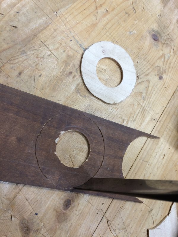
Think of all the band saws you could make once you have a band saw.
Lately, it's been just about every piece I have made that I wish I had a bandsaw.
https://vimeo.com/182253583
I set it up with the new motor. Works well.
I really need a table though and a safety enclosure.
That's impressive. That's slower than you want it though? Seemed a little slow to me. That's probably because the only one I ever used was in school. Industrial grade machines there.
Looks like it will absolutely serve though. Nice work. Again.
RE: speed
What size are your pulleys? The picture of the pulley on the motor seems tiny. Use your pulley sizes to set your speed.
I think I could have fed the wood into the blade faster. I was going slow because I was honestly terrified of the saw without an enclosure around those huge spinning wheels. So I put almost no pressure on the blade with my feed rate. I didn't want to upset the saw and have it tear my face off.
And as for the pulleys, I didn't have the right size for the speed I wanted, but it was going to have to be something like 6 inches diameter and pulleys that large were a bit more expensive on Ebay. I still needed to buy a pulley to go with my new $5 motor, but it was only $10 instead of like $25 for a giant pulley to go on the old motor. All that being said, I agree you want to adjust pulley size to get the speed you want.
I was honestly terrified of the saw without an enclosure around those huge spinning wheels.
Totally with you on this one!
Looks really good so far. I am loving this whole thing.
So after all this time i read the thread title as: Building a bandsaw on the cheap from mostly sacred wood
Seems appropriate.
Glatt, this guy is a man after your own heart. You should check out his channel
[YOUTUBE]UYcwWb0-evc[/YOUTUBE]
Thanks. I'll check it out.
My wife was out of town for the weekend, and the kids were away for most of Saturday at a band competition. I had time to get some work done. And I am getting close, so I'm motivated.
I wanted to get the table done this weekend, and the first step Saturday is to make these little flying saucer bolt heads to clamp the trunnions down. They need to be the same thickness as the trunnion supports, so I grab some of the leftover boards I had glued up to make those. They are an awkward shape. I could really use a band saw to cut these out. Funny thing about that, I think I now have a band saw I can use.
[ATTACH]57919[/ATTACH]
I cut out and glued down the paper templates to the stock. Then I clamped a scrap piece of quarter inch thick plywood to the band saw frame.
[ATTACH]57920[/ATTACH]
I cut them out on the band saw and they look great! I have a band saw!
[ATTACH]57921[/ATTACH]
I cleaned them up and smoothed them out on my son's disc sander.
[ATTACH]57922[/ATTACH]
The trunnion plans call for multiple layers glued up in a sandwich to leave an open slot that the locking bolts can move around in.
[ATTACH]57923[/ATTACH]
I used the table saw to cut up some more of that maple bed frame I dug out of the trash last month. I cut it to the proper thickness and took some off each side so I can remove the finish as I get down to the proper dimension.
[ATTACH]57924[/ATTACH]
I marked out the upper and lower curves of the trunnions using a compass set to a different radius for each curve.
[ATTACH]57925[/ATTACH]
And then I cut each one out on the band saw! This saw is working great!
[ATTACH]57926[/ATTACH]
I cleaned these up on my son's disc sander to get the curves nice and smooth.
[ATTACH]57927[/ATTACH]
For the center parts, a slat from that bed frame is the perfect thickness. So I grab one and sand the finish off on the belt sander.
[ATTACH]57928[/ATTACH]
Then I glued the templates down on that slat.
[ATTACH]57929[/ATTACH]
And cut them out on the band saw! I love saying that.
[ATTACH]57930[/ATTACH]
I arranged them in order and started to glue them up.
[ATTACH]57931[/ATTACH]
Clamped them to dry.
[ATTACH]57932[/ATTACH]
That evening, I cleaned up the dried glue squeeze out and tested the fit on the saw. They moved smoothly and clamped down tight. Nice.
[ATTACH]57933[/ATTACH]
Late Sunday morning, with the trunnions finished, I turned my attention to the table itself. The table is supported by a sub-table that is attached to the trunnions. So I dug around for a scrap of plywood I could use for a sub table. Towards the bottom of my pile of scraps, I found a beautiful piece of furniture grade 3/4 inch plywood. I don't remember where this came from, but I've got two of them, and they are gorgeous. So I cut it to size and laid out the dimensions on the work piece.
[ATTACH]57946[/ATTACH]
Again, I find this is most easily cut out on the band saw. I have to be careful not to get cocky about having a band saw now. The uncovered spinning wheel of death is right next to my face as I use it.
[ATTACH]57935[/ATTACH]
With the sub table cut out, I screw through the trunnions and into the edge of the sub table to support it. This is testing the fit on the frame.
[ATTACH]57936[/ATTACH]
The finished table top is attached with screws through the sub table and also screws driven diagonally through the trunnions. So I draw an angled line on the trunnions that will miss the existing screws and, while keeping an eyeball on the bubble in the level of my drill, I drill an angled hole through the trunnion. I do this 4 times.
[ATTACH]57937[/ATTACH]
Two weeks ago, while I was driving through the neighborhood, I saw a large, dishwasher-sized, chest of plastic drawers by the side of the road. It was on caster wheels, and the wheels looked really nice. So after driving by it a few times, I stopped to wrestle it into the back seat of my car. It was smelly. It had been in a flooded basement or something. But the wheels were nice, and I noticed that the top was in really nice shape. It was about an inch and a half thick particle board covered with melamine on both the top and bottom, and all the edges were finished with a nice plastic or rubber molding. And most importantly, it looked like it was the exact same size as a band saw table. So I took it all apart. Saved the wheels. And saved the top, and pitched the rest of the smelly mess away. The top cleaned up very nicely and had no odor. When I got the top into my shop with the plans in front of me, I could see it was 2 cm wider than the plans called for. Close enough. I'll keep the 2 cm, and save that finished edge. The length though is about 6 inches too long. So that's the only thing I have to cut to make it the finished size.
[ATTACH]57938[/ATTACH]
While I had it on the table saw to cut that edge, I cut a notch for feeding a band saw blade into the hole in the center as I change blades in the band saw. And I use a router in the center to form the lip that a blade insert will rest on.
[ATTACH]57939[/ATTACH]
Then I moved it to the band saw to cut the hole for the blade in the center.
[ATTACH]57940[/ATTACH]
I squared the corners with a chisel.
[ATTACH]57947[/ATTACH]
I placed the sub table assembly upside down on the bottom of the finished table top and got it all lined up with the measurements in the plans, while accounting for those 2 extra centimeters in width. As I was doing this, I almost forgot to put the clamp down bolts in place in the trunnions. But I remembered. Then I screwed everything down.
[ATTACH]57943[/ATTACH]
I moved the table to the band saw, and fed the blade through the saw kerf in the table top to get it onto the frame. I tested setting it at an angle and clamped it down. It worked great. Nice and solid.
[ATTACH]57944[/ATTACH]
But most of my work will be done with the table set in the level position, so I set the table square to the blade and drew a line across the joint between the trunnion and trunnion support to mark the 90 degree line up.
[ATTACH]57945[/ATTACH]
There is still a fair amount left to do. I have to make the enclosures. And I need to bolt the motor to the frame, instead of using temporary clamps, and I need to do the electrical stuff. Right now I plug it in to start it and unplug it to stop it
This is making me a little hot...
I did about an hour of electrical work last night. And for a change, my daughter came down into the shop to see what I was doing, and she helped me a bit. It was nice. (Although I got a little distracted when she was helping me, and forgot to take pictures as we were going along.)
I started off by spreading out all the stuff I thought I would need. I had dug a power strip out of the trash at work. We have been undergoing renovations in phases at work, and each floor is tasked with cleaning out their stuff before they move to another floor temporarily as their original floor gets worked on. Anyway, people are freaking lazy, and throw away lots of perfectly good stuff instead of packing it up. So I dug a power strip with a long cord out of a trash bin outside somebody's office one day. That's the gray power strip. The black power strip belonged to my FIL, and it's too ugly to make it into use in our house, so I'm going to cannibalize its cord. All these cords are 14 gauge. They should be enough to run the saw with its 9 amp motor.
[ATTACH]57971[/ATTACH]
The power strip from work has 3 philips head screws and 3 tamper proof screws. I find that the tamper proof screws can be removed if I tighten them a hair to break the grip of the threads, and then press down really hard as I slowly back them out.
[ATTACH]57972[/ATTACH]
I had to break apart the little circuit board inside to cut the wires neatly. This shot is for tw, not that he comes to this thread. It looks like the only electronic components in this power strip is a 5A fuse and maybe that's a capacitor.
[ATTACH]57973[/ATTACH]
Back to the band saw, I need to use my bit and brace to drill a clean hole deep enough to get through the frame. A spade bit in a power drill also would have worked, but they aren't as clean.
[ATTACH]57974[/ATTACH]
I'm going to put a switched outlet on the rear of the frame and switch it with a switch mounted on the front of the frame. Here I am about to put a cable clamp on the side of the outlet's metal box. The power cord will exit out of this side hole and get plugged into the house.
[ATTACH]57975[/ATTACH]
I stripped a segment of cable from my FIL's power strip to pass through the frame and into each box on either side of the frame.
[ATTACH]57976[/ATTACH]
The box is centered over the hole in the wood. So this wooden hole will act as a bushing to keep the cable from getting cut rubbing against the sharp edge of the box. If this was a box mounted in the wall of a home, I am supposed to have a clamp here to keep the cable from being tugged on, but on this saw, it will be completely encased in the frame and can't be tugged on. I ground the box with the green wire because it's there.
[ATTACH]57977[/ATTACH]
And then my daughter joined me, and I stopped taking detailed pictures.
This shot shows the outlet on the rear of the saw and the switch on the front of the saw. The motor is plugged into the outlet, and so is a goose necked lamp.
[ATTACH]57979[/ATTACH]
I attached the goose neck lap by screwing through the plastic of the spring clamp on the thing.
[ATTACH]57978[/ATTACH]
Video of the switch in action.
[YOUTUBE]EszYZpDzOt0[/YOUTUBE]
[YOUTUBEWIDE]EszYZpDzOt0[/YOUTUBEWIDE]
Excellent work, bro. And very clean and tidy too. The hand drill choice is indicative of your thoughtful approach to this project.
I am a huge fan of glatt.
And not just this thread. You are truly admirable. I'm sure reading that embarrasses you, but that's just too bad.
I'm hoping you have chronic halitosis or something. Fucking boy scout. ;)
glatt - this is ridiculously cool. Outstanding work.
Thank you!
I can almost taste it, I'm so close. It feels like it anyway. I think in reality the enclosure is going to be a lot of work.
The skills you learned and honed along the way... priceless! :notworthy
Remember to start a new project before this is finished so you have something to move right into, that way you can avoid the post project let-down. That's what my teacher told me.
Here's your next DIY: Thickness sander
http://lumberjocks.com/projects/7641Oh the dust! I thought the planer was bad. :p:
I'm considering a dust collector as my next project.
Excellent work, bro. And very clean and tidy too. The hand drill choice is indicative of your thoughtful approach to this project.
I am a huge fan of glatt.
And not just this thread. You are truly admirable. I'm sure reading that embarrasses you, but that's just too bad.
I'm hoping you have chronic halitosis or something. Fucking boy scout. ;)
I'm quite a fan myself. He had me at homemade wooden kayak. I was kinda holding out hope that maybe he beat his kids or something, but, halitosis is prolly better. Less beaty.
For a while I was substituting hummus as a spread on my sandwiches instead of mayo, and after a while my wife complained of my bad breath. So I switched back to mayo and she said my breath was ok again.
Pretty sure my breath doesn't smell.
Drat!
3 nipples?
Webbed feet?
Close talker?
That must be code for he beats his kids.
Close talker...:lol2:
I remember that episode of Seinfeld.
When you're done, you could pick up a few bucks on the side...
[YOUTUBE]jP9gE48J04E[/YOUTUBE]
That's just a little terrifying. So my saw will take my arm off in less than a second if I shove my arm in there.
They aren't kidding when they tell you to adjust the blade guide to only a quarter inch above the work piece so you can't cut an appendage off.
No way could I do that for eight hours.
I got bored about thirty seconds in.
He'd be several cuts past the mistake before he missed that thumb.
His thumb would be wrapped and shipped by then.
Alton Brown would be doing a special on cooking the thumb by then.
Thumb removal would have become popular with everyone's parents by then, while all the kids would have already moved on to the latest trend of waxed butt moustaches.
Salvation Armys across the nation would be full up with thumbs by then, waiting for a surge from ironic hipsters.
You'll be able to buy over the counter thumb removal CRISPR technology at gas stations and mini marts next to the no-doz, butt mustache wax, and condoms.
Sorry glatt, didn't mean to derail your build thread, just add a little levity.
Now back to the fantastic build.
Derailments like this one are one of my favorite things about the Cellar.
I mean, who woulda thunk we coulda got this much levity out of a simple thumb comment.
You guys rock.
Nah. No worries. Have fun in the thread. I'll get it back on the track when I am ready. I enjoyed showing the meat video to my kids.
Sorry glatt, didn't mean to derail your build thread, just add a little levity.
Now back to the fantastic build.
Fuck that shit, it's thumb jokes until he gets his lazy ass down to the shop and starts building that cover that he is avoiding.
I'm half tempted to start a thread, "Building a bandsaw on the cheap from mostly detached thumbs" but I'm too busy procrastinating.
There is a saying about procrastination. One day I'll look it up.
I'm half tempted to start a thread, "Building a bandsaw on the cheap from mostly detached thumbs" but I'm too busy procrastinating.
I heard a rumor that foot3 is super clumsy. He's all thumbs.
ALSO DID YOU KNOW... in the movie Spy Kids, the bad guy's henchmen were called Thumb-Thumbs.
Fuck that shit, it's thumb jokes until he gets his lazy ass down to the shop and starts building that cover that he is avoiding.
I did a little work a few weeks ago and need to update this thread. It's slow going though, because I'm running in to problems again where the plans don't match my saw as built. And I have trouble visualizing the piece I'm making and how it fits with the saw until after I have made the piece and it doesn't fit. Then I can see what needed to be wider or longer, or whatever.
Back at the beginning of the month on October 2nd, I dug around for a nice scrap of quarter inch plywood to serve as the most visible part of the saw. The upper wheel cover. It will feel good to have this cover in place because that big spinning wheel of death is just a couple of inches from my nose as I use the saw.
[ATTACH]58191[/ATTACH]
I cut it to shape on the table saw except for the very last inch or two of the inside corner. For that, I went over to my BANDSAW to cut it out.
[ATTACH]58192[/ATTACH]
I cut the first simple edge board to length and glued it in place
[ATTACH]58193[/ATTACH]
The next edge board has a little notch cut out of it to make space for the blade guide, which slides up and down.
[ATTACH]58194[/ATTACH]
More edges glued up.
[ATTACH]58195[/ATTACH]
This is a complicated piece to fit around the different layers of the frame.
[ATTACH]58196[/ATTACH]
Glue up
[ATTACH]58197[/ATTACH]
These diagonal pieces need to have a bird's mouth joint cut into them to help hold the corners together. A band saw is the perfect tool to cut those, and I just happen to have one.
[ATTACH]58198[/ATTACH]
Gluing up some more
[ATTACH]58199[/ATTACH]
Laying out the lines for the rear plywood piece. This has to fit over the wheel and axle, so has notches cut out of it. I cut it out on the band saw.
[ATTACH]58200[/ATTACH]
The motor was hanging off the end of the shelf. I guess the plans were designed for a different motor shape. I needed to extend the length of the shelf.
[ATTACH]58201[/ATTACH]
and here you can see that I have changed the pulley to slow the blade speed down to the speed I want. So you can add $10 to the cost. I still need to actually bolt the motor down, but first I want to finish any tuning I need to do of the saw.
[ATTACH]58202[/ATTACH]
The next weekend, I clamped the cover in place to test the fit. It doesn't fit. It rubs in at least two places. Sigh. At least it looks good.
[ATTACH]58203[/ATTACH]
The oil can blade guard is too close to the cover. I think this is because I made the wheels slightly larger than the plans called for so this would be a true 16 inch band saw.
[ATTACH]58204[/ATTACH]
So I take the cover to the drill press to hog out some material. I need to remove enough material while still leaving enough to provide strength.
[ATTACH]58205[/ATTACH]
The material is removed. The blade guard doesn't rub now.
[ATTACH]58206[/ATTACH]
You should have been a documentarian.
The cover is held in place with little tabs that fit into holes drilled in the frame. I tapered the dowel part of these tabs, and then located the correct placement for them.
[ATTACH]58207[/ATTACH]
The tabs glued in place.
[ATTACH]58208[/ATTACH]
And checking the fit, they are too close together to fit around the leaf springs.
[ATTACH]58209[/ATTACH]
So I trim them both with a hand saw and remove the waste with a chisel.
[ATTACH]58210[/ATTACH]
And I test the fit again. I can get the thing around the wheel without obstructions. Nothing is rubbing! But the tabs don't reach deep enough in the frame. I think it's a metric vs. inch thing. My frame is made of 3/4 inch boards. Who knows what Matthias used in Canada? I don't. But I need to get about 3/16th of an inch closer and I can't.
[ATTACH]58211[/ATTACH]
I need to cut these notches in the cover sides deeper. But then it won't fit over the wheel any more. The front of the cover will hit the front of the wheel. It won't be deep enough. So I think I'll need to cut some strips to glue to the edge of the cover to give me the depth I need, and then cut the notches deeper.
So that's where I am. I haven't touched this project in 8 days.
It's almost to the point that I'm considering just building the cover over from scratch again instead of trying to shim my way to a good fit. But I used my best scrap of plywood, and it looks so nice.
If it were me I'd cob it and slap a coat of paint on the offending area, but it wouldn't bug me every time I used it.
is it that the plywood needs to move to the left in your photo, or the peg needs to move to the left, or both?
In either case I'd just rip a few strips of 3/16" thick material off a 1x and glue that to either the ply or the frame.
Probably a metric/standard issue. Metric ply is a shade larger than 1/4, 3/8. or 1/2 and standard ply is a shade under 1/4, 3/8, 1/2" etc. Not sure it would add up to 3/16" though. Probably it's the nut behind the wrench...
Mostly the peg needs to move to the left. I'm gonna make new thicker peg things that reach further over so they have some meat to dig into.
Tempted to go down there tonight, but that glass of wine I had earlier makes power tools a bad idea. I may just catch up on Stranger Things.
My dad is coming to visit in early December and I'd like a basically finished saw then. Time's ticking.
can you just saw the existing peg flush then drill a new hole, say 5/32" and use a 16d common nail with the head cut off as a pin?
In theory, yes. In practice, I put a pretty big taper on that peg so it would find its hole even when it is off by an eighth or so. I'll have four pegs that have to find their holes simultaneously. So built in slop is good here.
I knocked out a new back for the cover. Can't make the peg holder things though because I am out of dowels.

Looks like it was made by a wino. :lol2:
Can't make the peg holder things though because I am out of dowels.
Wood pencils?
Nevermind, prolly too fragile.
Tinkered with the band saw for several hours today, but nothing to show for it.
The table is made of particle board, and I had cut through the plastic laminate top and bottom to make it the right size. This left an exposed particle board edge. That stuff can suck up moisture and start crumbling like nobody's business. So I found an old partial can of oil based varnish and sealed the cut edges of the particle board.
I made new tabs to go on the top cover, but didn't install them yet. It was a rare moment of clarity. The saw has a bit of a vibration to it, so I wanted to figure out what was vibrating and fix it before locking in on a cover size. You can see the motor shaking a bit too as the frame shakes.
I read in that Bandsaw book Foot recommended that you should align the wheels so they are co-planer and not rely on the crowned wheels so much to align the saw blade. So I got out my straight edge to fine tune that. I figured I might need to shim the wheels with some washers to get them perfectly lined up. When I lined the straight edge up with the bottom wheel, the top wheel was a full 9mm out of alignment further back. WTF? I have no idea how that happened. Did I measure the shaft wrong? Is it a metric thing with the layers of the frame? I don't know, but I do know that I need to fix it before I finish the cover. It's going to mess with the cover a lot to move that top wheel 9 mm forward.
I took the blade off the saw and ran just the powered bottom wheel. The vibrations were still there. I took the bottom wheel off and ran just the motor. No vibrations. So I got out my dial indicator and measured the pulley on the powered wheel. As I slowly rotate it, the needle goes 5 thousandths in one direction and then 15 thousandths in the other. The pulley is 20 thousands out of round. I wonder if that's enough to cause those vibrations? I bet it is. So I'm attempting to turn the pulley again to get it nice and round. I think when I turned it before, my chisel was just riding up the hump and then down into the hollow. I hold it fast to the tool rest more this time as I turn the bottom of the pulley.
So the saw is basically completely disassembled right now as I try to tweak this stuff.
Even in the best of situations, it's an iterative process. It's worth the effort IMO. You inspired me to tackle my store-bought saw and for the first time in 10 years the thing cuts like it is supposed to. Duginske's book is great.
I figured out my misalignment problem. This vertical peice was built exactly according to the plans in metric. But apparently it was supposed to be as wide as those two 3/4 inch boards underneath it. I guess metric lumber is thinner than the US lumber I used.

So I just need to cut a 9mm thick shim to go in there. And things should line up.
Although maybe that will mess up the blade guide fit. I need to ponder this.
It happens to the best of us, at least your bandsaw didn't go
plowing through the atmosphere, continuing out beyond Mars and now could be orbiting the sun...
This article begs to be re-written, Onion style, with Glatt exchanged for NASA and bandsaw for rocket and Mrs; Glatt as the JPL Admin. Bu I'm too tired right now.
http://edition.cnn.com/TECH/space/9909/30/mars.metric.02/
CNN) -- NASA lost a $125 million Mars orbiter because a Lockheed Martin engineering team used English units of measurement while the agency's team used the more conventional metric system for a key spacecraft operation, according to a review finding released Thursday.
The units mismatch prevented navigation information from transferring between the Mars Climate Orbiter spacecraft team in at Lockheed Martin in Denver and the flight team at NASA's Jet Propulsion Laboratory in Pasadena, California.
Lockheed Martin helped build, develop and operate the spacecraft for NASA. Its engineers provided navigation commands for Climate Orbiter's thrusters in English units although NASA has been using the metric system predominantly since at least 1990.
No one is pointing fingers at Lockheed Martin, said Tom Gavin, the JPL administrator to whom all project managers report.
"This is an end-to-end process problem," he said. "A single error like this should not have caused the loss of Climate Orbiter. Something went wrong in our system processes in checks and balances that we have that should have caught this and fixed it."
The finding came from an internal review panel at JPL that reported the cause to Gavin on Wednesday. The group included about 10 navigation specialists, many of whom recently retired from JPL.
"They have been looking at this since Friday morning following the loss," Gavin said.
The navigation mishap killed the mission on a day when engineers had expected to celebrate the craft's entry into Mars' orbit.
After a 286-day journey, the probe fired its engine on September 23 to push itself into orbit.
The engine fired but the spacecraft came within 60 km (36 miles) of the planet -- about 100 km closer than planned and about 25 km (15 miles) beneath the level at which the it could function properly, mission members said.
The latest findings show that the spacecraft's propulsion system overheated and was disabled as Climate Orbiter dipped deeply into the atmosphere, JPL spokesman Frank O'Donnell said.
That probably stopped the engine from completing its burn, so Climate Orbiter likely plowed through the atmosphere, continued out beyond Mars and now could be orbiting the sun, he said.
Climate Orbiter was to relay data from an upcoming partner mission called Mars Polar Lander, scheduled to set down on Mars in December. Now mission planners are working out how to relay its data via its own radio and another orbiter now circling the red planet.
Climate Orbiter and Polar Lander were designed to help scientists understand Mars' water history and the potential for life in the planet's past. There is strong evidence that Mars was once awash with water, but scientists have no clear answers to where the water went and what drove it away.
NASA has convened two panels to look into what led to the loss of the orbiter, including the internal peer review panel that released the Thursday finding. NASA also plans to form a third board -- an independent review panel -- to look into the accident.
Metric system used by NASA for many years
A NASA document came out several years ago, when the Cassini mission to Saturn was under development, establishing the metric system for all units of measurement, Gavin said.
The metric system is used for the Polar Lander mission, as well as upcoming missions to Mars, he said.
That review panel's findings now are being studied by a second group -- a special review board headed up by John Casani, which will search for the processes that failed to find the metric to English mismatch. Casani retired from JPL two months ago from the position of chief engineer for the Lab.
"We're going to look at how was the data transferred," Gavin said. "How did it originally get into system in English units? How was it transferred? When we were doing navigation and Doppler (distance and speed) checks, how come we didn't find it?"
"People make errors," Gavin said. "The problem here was not the error. It was the failure of us to look at it end-to-end and find it. It's unfair to rely on any one person."
I even bought a metric tape measure and used metric units every time I measured anything.
The plans said that US dimensional lumber could be used for the frame, but I wish I had bought a thickness planer and run the boards through to make them all the standard metric thickness when I started this thing because this is the third time I have run into an issue with the frame being thicker than the plans called for and it caused a problem.
At least it's in my basement where I can fix it. If it was on Mars, I would be out of luck.
And stationary rather than travelling at 24,000 KPH
;)
I spent all weekend taking it apart and tweaking it.
The biggest improvement in eliminating vibrations was re-balancing the wheels. It's possible there was moisture in them from the glue up and as the glue dried and the wood around the glue dried, the balancing I did before had to be tweaked a little. Although it's also possible that I just did a shoddy job last time.
Also, a big improvement was that the pulley on the drive wheel was 20 thousands of an inch out of round. So I spun that wheel up again and very carefully used a chisel to get the pulley groove round. I could feel the chisel wanting to rock back and forth with the pulley as the wheel rotated each time, so I really held it tightly against the tool rest and just eased it ever so slightly against the pulley to nibble gently away at the higher side as it came around. I could hear a bit of a pulsating cutting sound as it only nibbled away at the high side. Once the sound became constant cutting, I stopped. When I measured it again, it was 5 thousandths out of round.
Then I turned my attention to getting the wheels lined up better. And I started taking pictures.
To get the top wheel directly over the bottom wheel, I needed to pull it forward by 8-9 mm.
So I started by removing the brackets that hold the entire top wheel assembly in place. Fortunately they are just screwed on. No glue.
[ATTACH]58280[/ATTACH]
Then I cut two shims 8 mm thick.
[ATTACH]58281[/ATTACH]
I glued the shims to the uprights.
[ATTACH]58282[/ATTACH]
And clamped them to dry
[ATTACH]58283[/ATTACH]
Maybe this was another metric vs. USA issue, or maybe it's just a bad detail in the plans, but the notch I cut in the table support to make room for the lower powered wheel isn't long enough to pull the wheel forward and remove it from the shaft. To remove the lower wheel, you have to take the table off. So after removing the table to get the wheel off, I chopped the notch a little to make getting the wheel off easier in the future.
[ATTACH]58284[/ATTACH]
And here's is the top wheel reassembled after putting that shim in.
[ATTACH]58285[/ATTACH]
I don't have enough hands to hold a long straight edge and take a picture at the same time, but this picture is supposed to show that the top and bottom wheel are coplaner now. Yay.
[ATTACH]58286[/ATTACH]
With the top wheel pulled forward, the blade guard made out of the oil can doesn't fit around the wheel any more. So I have to make a bigger one. Fortunately, I have another one of those big olive oil cans in my junk pile. This time, I plan to use the English side of the can.
[ATTACH]58287[/ATTACH]
It will be as wide as this blue tape.
I didn't get a shot of the completed guard yet. But it's done and installed.
[ATTACH]58288[/ATTACH]
The saw blade is tracking well now, and the vibrations are much improved.
Now I have to work on the cover again.
Working the last couple of nights on another cover. This time I'm measuring from the frame instead of following the plans. It should fit, and I will be embarrassed if it doesn't.
The front cover is a cm wider.
[ATTACH]58321[/ATTACH]
And the sides I'm gluing on are 2 cm deeper to account for how far forward I moved the top wheel and to provide a bit of clearance.
[ATTACH]58322[/ATTACH]
As I was making the cover, I noticed that when cutting bird's mouth joints on the diagonal boards that support the edges of the cover, the cuts weren't square in the front-to-back vertical axis. It was off by about an eight of an inch over 5 inches. Pretty bad. The table supports were a few thousandths different from one other and the support arm was too. And they actually lined up just wrong to multiply the error. Anyway, I put a couple broken off hacksaw blades under the support arm to act as shims, and brought the table into squareness.
Here, I'm pointing at the ends of the hacksaw shims barely visible in the picture between the frame and the table support. Using a hacksaw blade as a pointer.
[ATTACH]58324[/ATTACH]
And checking the squareness of the table to the blade now. It's still not absolutely perfect, but it's close enough. Maybe off by 1/16th of an inch over a foot.
[ATTACH]58325[/ATTACH]
He needs a lathe...
Yes...
Yeah, but where can you get excelsior these days? Everything is styrofoam peanuts now.
And checking the squareness of the table to the blade now. It's still not absolutely perfect, but it's close enough. Maybe off by 1/16th of an inch over a foot.
That's nearly a quarter of an inch to me.
This is the state of my art in the shop right now.
[YOUTUBE]1T9lums4sEY[/YOUTUBE]
[YOUTUBEWIDE]1T9lums4sEY[/YOUTUBEWIDE]
That click click clicking you hear is the weld in the blade hitting the blade guides. I have little experience with band saws. How normal is that?
Usually blades are welded by heating red hot and pushing them together which causes a bulge in both sides. That's why the big Do-Alls have a welder and a grinding wheel to clean them up. You can grind off that extra weld on both sides od the blade if it was welded properly.
Duginske describes how to deal with that in his book
Working a little on the lower wheel enclosure. this will stablize the saw by giving it a wider base and also help collect saw dust.
I used the band saw to cut these two vertical side pieces of the enclosure, and I measured from the machine while just eyeballing the plans.
[ATTACH]58492[/ATTACH]
The band saw isn't technically done, but I keep using it as if it is.
I've been using a socket wrench to tilt the upper wheel and tension the blade. I got sick of doing that so I focused last night on making a crank for tensioning the blade.
I cut a wooden piece to mimic a socket wrench.
[ATTACH]58601[/ATTACH]
Rounded the inside sharp edges over with a rasp.
Then I drilled an undersized hole in it and pressed one of those long skinny coupler nuts into that hole. Used the vise to press it in.
[ATTACH]58604[/ATTACH]
Then I made a spinny knob to loosely bolt to the end of it. I had a galvanized bolt to attach that spinny knob, which is great because the galvanization is rough enough to lock the nut in place without the nut being tightened down. It works great. Plenty of leverage to tension the blade.
[ATTACH]58602[/ATTACH]
Next I wanted a knob to cover the end of the upper blade tilting bolt.
I sketched something out on a scrap piece of paper and glued it to a scrap piece of wood I got from a thrown out table. I think this was a leg brace to attach a leg to the apron of the table. Anyway, it already had a proper sized hole drilled for the bolt head. I centered my drawing over that hole.
[ATTACH]58605[/ATTACH]
I cut it out on the band saw and sanded the ugly stain off.
[ATTACH]58606[/ATTACH]
And I pressed it over the blade tilt bolt head. Basically jammed it on there.
[ATTACH]58607[/ATTACH]
Both of them work great! And I don't have to go digging for the proper sized socket any more.
Well done, Sir. :notworthy
Glatt, any idea how many hours ya got in this project?
I was trying to keep some track of that. I could go back through this thread and add it up. It's a lot. If I were to go into business doing this, I would starve.
The next one would go much faster... because he has a bandsaw. :thumb:
Made a lot of progress over the holiday weekend. I built a cover to go around the pulley and the belt. Safety issue there. Only a matter of time before somebody got their hair caught in that belt.
[ATTACH]58649[/ATTACH]
And then I wanted to make a front panel for the lower wheel. The drawings for this part were pretty complicated, and I've learned to ignore the plans when that's the case. So I cut up bits of cardboard and taped them together until they fit the opening.
[ATTACH]58650[/ATTACH]
Then I traced that on some plywood an cut that out. Not shown, is gluing some strips of wood to the back side to stiffen it.
[ATTACH]58651[/ATTACH]
This is a random bit of enclosure that fits under the table against the frame. It has to be tapered to fit the frame taper. I weigh the thing down with a couple of quarts of varnish to let the glue dry.
[ATTACH]58652[/ATTACH]
I needed a hook to hold the lower front cover closed. I could drive to the hardware store to waste half an hour and $3 to buy one, or just spend five minutes in the shop to make one for free.
Grab a coat hanger off cut I had saved from a previous project I can't remember.
[ATTACH]58653[/ATTACH]
Bent it into a hook shape with a pair of needle nosed pliers.
[ATTACH]58654[/ATTACH]
Cut it free and found a couple of screws that fit.
[ATTACH]58655[/ATTACH]
Installed it.
[ATTACH]58656[/ATTACH]
I had to plane down the board you see in the foreground of that last shot so it would fit under the table as you close the panel. It was sticking up just a little too far and was bonking into the table, so I put a very slight taper on it.
There was a fair amount of trimming and fiddling here and there to get components to fit right throughout the entire process of making this saw.
Front view.
[ATTACH]58657[/ATTACH]
Rear lower wheel has a sloped cover to direct sawdust down to the bottom.
[ATTACH]58658[/ATTACH]
This band saw is mostly done now.
There is a small panel to fit around the opening under the table around the blade guide. And mainly I need to build a sturdy base for it. With caster wheels. This undersized bed side table I dug out of the trash isn't very solid. And I will probably varnish it.
Awesome.
I have enjoyed this project of yours immensely.
Cool, now make another bandsaw from clear plexiglass. :lol2:
Sweet! This has been most enjoyable AND educational.
It looks like it was obviously homemade... by a craftsman. :thumb:
Goddamn you motherfuckers are handy.
snip--
This band saw is mostly done now.
There is a small panel to fit around the opening under the table around the blade guide. And mainly I need to build a sturdy base for it. With caster wheels. This undersized bed side table I dug out of the trash isn't very solid. And I will probably varnish it.
Got something for you:
[SIZE="4"]
ボール盤台座と着脱キャスタ[/SIZE]
I think you'll love it.
[YOUTUBEWIDE]Z9bOxTyCrBg[/YOUTUBEWIDE]
It was a great ride!
Who is next?
Got something for you:
I think you'll love it.
That's pretty clever. I'll try to incorporate a feature like that.
I just went through the thread adding up the time I probably spent on each step, and I think I put about 115 - 135 hours into this project. I didn't keep clear enough records to know for sure. Figure 3 work weeks. And I spent about $300 on materials for it. To pay myself minimum wage, I would have to charge $2,040 for this saw.
Laguna sells a 16 inch band saw for $3,499, so I'm cheaper than that.
But Grizzly sells one for $850.
The next one you could do in less than half the time, though
The skills and knowledge you got from this project are worth a few grand.
Plus the pride of accomplishment and the respect of your peers... who will ask you to do things for them now you have a bandsaw. :D
Hammer a copper penny into a flat oval, bang a 1 into it, and affix it with copper tacks. Then make a 2nd one, 3td, etc, and sell it to someone.... Like me or foot or Bruce..... Defray your cost.
I will once I own a home again. Maybe 3 or 4 years hence
Since this thread was so popular it was suggested someone start a new thread of a project they're building.
While surfing the web I spotted an ad saying, "Build the Best Saw in the World". Lots of hoopla each ending
with "Best Saw in the World". So I go to their site and they'll sell you detailed plans, an instruction video, and
bill of materials for "Best Saw in the World", only $40.

WTF? Saw? That doesn't look like a saw?
Then they show what the "Best Saw in the World" can do.

Dude, that ain't what a saw does.
Then they say it can be controlled from your computer or laptop.
OK it's a computer controlled milling machine. I wonder how much it would cost to build it, 3 lead screws, 3control boxes
with 3 stepper motors can't be cheap.
Then you have to write the programs, I know it's not that simple. I did that for a living for many years.
Interesting, but that ain't no saw, Bubba.:headshake
linkBut it madeja clickit - - win.
That'll do, saw, that'll do.
The guy who designed my band saw just made a bigger one. 20 inches.
He put together a 20 minute video showing how he did it. It's basically step by step how I made mine, with very slight differences here and there. I forgot how much work it was.
[YOUTUBE]aiDJp6utmUM[/YOUTUBE]
https://www.youtube.com/watch?v=aiDJp6utmUMWe didn't forget. You totally rocked that thing.
That's a lot of fabricating.
If you had built a jigsaw...
That's $185 in today's dollars. About what a decent jigsaw
would cost today.Make this cut-out free!!
[size=1]For $17.50.[/size]
I wood if I had the chance.